The CLP Procedure
-
Overview

-
Getting Started
-
Syntax
-
Details
-
ExamplesLogic-Based PuzzlesAlphabet Blocks ProblemWork-Shift Scheduling ProblemA Nonlinear Optimization ProblemCar Painting ProblemScene Allocation ProblemCar Sequencing ProblemRound-Robin ProblemResource-Constrained Scheduling with Nonstandard Temporal ConstraintsScheduling with Alternate Resources10×10 Job Shop Scheduling ProblemScheduling a Major Basketball ConferenceBalanced Incomplete Block DesignProgressive Party ProblemStatement and Option Cross-Reference Table
- References
Example 3.9 Resource-Constrained Scheduling with Nonstandard Temporal Constraints
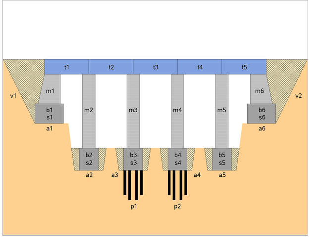
This example illustrates a real-life scheduling problem and is used as a benchmark problem in the constraint programming community. The problem is to schedule the construction of a five-segment bridge. (See Output 3.9.1.) It comes from a Ph.D. dissertation on scheduling problems (Bartusch, 1983).
Output 3.9.1: The Bridge Problem
The project consists of 44 tasks and a set of constraints that relate these tasks. Table 3.13 displays the activity information, standard precedence constraints, and resource constraints. The sharing of a unary resource by multiple activities results in the resource constraints being disjunctive in nature.
Table 3.13: Data for Bridge Construction
|
Activity |
Description |
Duration |
Predecessors |
Resource |
|---|---|---|---|---|
|
pa |
Beginning of project |
0 |
||
|
a1 |
Bxcavation (abutment 1) |
4 |
pa |
Excavator |
|
a2 |
Bxcavation (pillar 1) |
2 |
pa |
Excavator |
|
a3 |
Bxcavation (pillar 2) |
2 |
pa |
Excavator |
|
a4 |
Excavation (pillar 3) |
2 |
pa |
Excavator |
|
a5 |
Excavation (pillar 4) |
2 |
pa |
Excavator |
|
a6 |
Excavation (abutment 2) |
5 |
pa |
Excavator |
|
p1 |
Foundation piles 2 |
20 |
a3 |
Pile driver |
|
p2 |
Foundation piles 3 |
13 |
a4 |
Pile driver |
|
ue |
Erection of temporary housing |
10 |
pa |
|
|
s1 |
Formwork (abutment 1) |
8 |
a1 |
Carpentry |
|
s2 |
Formwork (pillar 1) |
4 |
a2 |
Carpentry |
|
s3 |
Formwork (pillar 2) |
4 |
p1 |
Carpentry |
|
s4 |
Formwork (pillar 3) |
4 |
p2 |
Carpentry |
|
s5 |
Formwork (pillar 4) |
4 |
a5 |
Carpentry |
|
s6 |
Formwork (abutment 2) |
10 |
a6 |
Carpentry |
|
b1 |
Concrete foundation (abutment 1) |
1 |
s1 |
Concrete mixer |
|
b2 |
Concrete foundation (pillar 1) |
1 |
s2 |
Concrete mixer |
|
b3 |
Concrete foundation (pillar 2) |
1 |
s3 |
Concrete mixer |
|
b4 |
Concrete foundation (pillar 3) |
1 |
s4 |
Concrete mixer |
|
b5 |
Concrete foundation (pillar 4) |
1 |
s5 |
Concrete mixer |
|
b6 |
Concrete foundation (abutment 2) |
1 |
s6 |
Concrete mixer |
|
ab1 |
Concrete setting time (abutment 1) |
1 |
b1 |
|
|
ab2 |
Concrete setting time (pillar 1) |
1 |
b2 |
|
|
ab3 |
Concrete setting time (pillar 2) |
1 |
b3 |
|
|
ab4 |
Concrete setting time (pillar 3) |
1 |
b4 |
|
|
ab5 |
Concrete setting time (pillar 4) |
1 |
b5 |
|
|
ab6 |
Concrete setting time (abutment 2) |
1 |
b6 |
|
|
m1 |
Masonry work (abutment 1) |
16 |
ab1 |
Bricklaying |
|
m2 |
Masonry work (pillar 1) |
8 |
ab2 |
Bricklaying |
|
m3 |
Masonry work (pillar 2) |
8 |
ab3 |
Bricklaying |
|
m4 |
Masonry work (pillar 3) |
8 |
ab4 |
Bricklaying |
|
m5 |
Masonry work (pillar 4) |
8 |
ab5 |
Bricklaying |
|
m6 |
Masonry work (abutment 2) |
20 |
ab6 |
Bricklaying |
|
l |
Delivery of the preformed bearers |
2 |
Crane |
|
|
t1 |
Positioning (preformed bearer 1) |
12 |
m1, m2, l |
Crane |
|
t2 |
Positioning (preformed bearer 2) |
12 |
m2, m3, l |
Crane |
|
t3 |
Positioning (preformed bearer 3) |
12 |
m3, m4, l |
Crane |
|
t4 |
Positioning (preformed bearer 4) |
12 |
m4, m5, l |
Crane |
|
t5 |
Positioning (preformed bearer 5) |
12 |
m5, m6, l |
Crane |
|
ua |
Removal of the temporary housing |
10 |
||
|
v1 |
Filling 1 |
15 |
t1 |
Caterpillar |
|
v2 |
Filling 2 |
10 |
t5 |
Caterpillar |
|
pe |
End of project |
0 |
t2, t3, t4, v1, v2, ua |
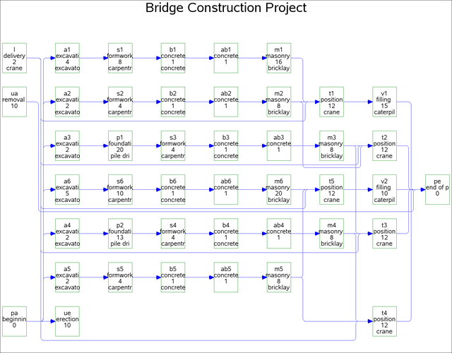
Output 3.9.2 shows a network diagram that illustrates the precedence constraints in this problem. Each node represents an activity and gives the activity code, truncated description, duration, and the required resource, if any. The network diagram is generated using the SAS/OR NETDRAW procedure.
Output 3.9.2: Network Diagram for the Bridge Construction Project
The following constraints are in addition to the standard precedence constraints:
-
The time between the completion of a particular formwork and the completion of its corresponding concrete foundation is at most four days:
![\[ f(\mr {s}i) \geq f(\mr {b}i) - 4, ~ ~ ~ i=1,\cdots ,6 \]](images/orcpug_clp0212.png)
-
There are at most three days between the end of a particular excavation (or foundation piles) and the beginning of the corresponding formwork:
![\[ f(\mr {a}i) \geq s(\mr {s}i) - 3, ~ ~ ~ i = 1,2,5,6 \]](images/orcpug_clp0213.png)
and
![\[ f(\mr {p1}) \geq s(\mr {s3}) - 3 \]](images/orcpug_clp0214.png)
![\[ f(\mr {p2}) \geq s(\mr {s4}) - 3 \]](images/orcpug_clp0215.png)
-
The formworks must start at least six days after the beginning of the erection of the temporary housing:
![\[ s(\mr {s}i) \geq s(\mr {ue}) + 6, ~ ~ ~ i = 1,\cdots ,6 \]](images/orcpug_clp0216.png)
-
The removal of the temporary housing can start at most two days before the end of the last masonry work:
![\[ s(\mr {ua}) \geq f(\mr {m}i) - 2, ~ ~ ~ i = 1,\cdots ,6 \]](images/orcpug_clp0217.png)
-
The delivery of the preformed bearers occurs exactly 30 days after the beginning of the project:
![\[ s(\mr {l}) = s(\mr {pa}) + 30 \]](images/orcpug_clp0218.png)
The following DATA step defines the data set bridge, which encapsulates all of the precedence constraints and also indicates the resources that are required by each activity.
Note the use of the reserved variables _ACTIVITY_, _SUCCESSOR_, _LAG_, and _LAGDUR_ to define the activity and precedence relationships. The list of reserved variables can be found in Table 3.6. The latter two variables are required for the nonstandard precedence constraints listed previously.
data bridge;
   format _ACTIVITY_ $3. _DESC_ $34. _RESOURCE_ $14.
          _SUCCESSOR_ $3. _LAG_ $3. ;
   input _ACTIVITY_ & _DESC_ & _DURATION_ _RESOURCE_ &
         _SUCCESSOR_ & _LAG_ & _LAGDUR_;
   _QTY_ = 1;
   datalines;
a1   excavation (abutment 1)             4  excavator       s1   .     .
a2   excavation (pillar 1)               2  excavator       s2   .     .
a3   excavation (pillar 2)               2  excavator       p1   .     .
a4   excavation (pillar 3)               2  excavator       p2   .     .
a5   excavation (pillar 4)               2  excavator       s5   .     .
a6   excavation (abutment 2)             5  excavator       s6   .     .
ab1  concrete setting time (abutment 1)  1  .               m1   .     .
ab2  concrete setting time (pillar 1)    1  .               m2   .     .
ab3  concrete setting time (pillar 2)    1  .               m3   .     .
ab4  concrete setting time (pillar 3)    1  .               m4   .     .
ab5  concrete setting time (pillar 4)    1  .               m5   .     .
ab6  concrete setting time (abutment 2)  1  .               m6   .     .
b1   concrete foundation (abutment 1)    1  concrete mixer  ab1  .     .
b1   concrete foundation (abutment 1)    1  concrete mixer  s1   ff   -4
b2   concrete foundation (pillar 1)      1  concrete mixer  ab2  .     .
b2   concrete foundation (pillar 1)      1  concrete mixer  s2   ff   -4
b3   concrete foundation (pillar 2)      1  concrete mixer  ab3  .     .
b3   concrete foundation (pillar 2)      1  concrete mixer  s3   ff   -4
b4   concrete foundation (pillar 3)      1  concrete mixer  ab4  .     .
b4   concrete foundation (pillar 3)      1  concrete mixer  s4   ff   -4
b5   concrete foundation (pillar 4)      1  concrete mixer  ab5  .     .
b5   concrete foundation (pillar 4)      1  concrete mixer  s5   ff   -4
b6   concrete foundation (abutment 2)    1  concrete mixer  ab6  .     .
b6   concrete foundation (abutment 2)    1  concrete mixer  s6   ff   -4
l    delivery of the preformed bearers   2  crane           t1   .     .
l    delivery of the preformed bearers   2  crane           t2   .     .
l    delivery of the preformed bearers   2  crane           t3   .     .
l    delivery of the preformed bearers   2  crane           t4   .     .
l    delivery of the preformed bearers   2  crane           t5   .     .
m1   masonry work (abutment 1)          16  bricklaying     t1   .     .
m1   masonry work (abutment 1)          16  bricklaying     ua   fs   -2
m2   masonry work (pillar 1)             8  bricklaying     t1   .     .
m2   masonry work (pillar 1)             8  bricklaying     t2   .     .
m2   masonry work (pillar 1)             8  bricklaying     ua   fs   -2
m3   masonry work (pillar 2)             8  bricklaying     t2   .     .
m3   masonry work (pillar 2)             8  bricklaying     t3   .     .
m3   masonry work (pillar 2)             8  bricklaying     ua   fs   -2
m4   masonry work (pillar 3)             8  bricklaying     t3   .     .
m4   masonry work (pillar 3)             8  bricklaying     t4   .     .
m4   masonry work (pillar 3)             8  bricklaying     ua   fs   -2
m5   masonry work (pillar 4)             8  bricklaying     t4   .     .
m5   masonry work (pillar 4)             8  bricklaying     t5   .     .
m5   masonry work (pillar 4)             8  bricklaying     ua   fs   -2
m6   masonry work (abutment 2)          20  bricklaying     t5   .     .
m6   masonry work (abutment 2)          20  bricklaying     ua   fs   -2
p1   foundation piles 2                 20  pile driver     s3   .     .
p2   foundation piles 3                 13  pile driver     s4   .     .
pa   beginning of project                0  .               a1   .     .
pa   beginning of project                0  .               a2   .     .
pa   beginning of project                0  .               a3   .     .
pa   beginning of project                0  .               a4   .     .
pa   beginning of project                0  .               a5   .     .
pa   beginning of project                0  .               a6   .     .
pa   beginning of project                0  .               l    fse  30
pa   beginning of project                0  .               ue   .     .
pe   end of project                      0  .               .    .     .
s1   formwork (abutment 1)               8  carpentry       b1   .     .
s1   formwork (abutment 1)               8  carpentry       a1   sf   -3
s2   formwork (pillar 1)                 4  carpentry       b2   .     .
s2   formwork (pillar 1)                 4  carpentry       a2   sf   -3
s3   formwork (pillar 2)                 4  carpentry       b3   .     .
s3   formwork (pillar 2)                 4  carpentry       p1   sf   -3
s4   formwork (pillar 3)                 4  carpentry       b4   .     .
s4   formwork (pillar 3)                 4  carpentry       p2   sf   -3
s5   formwork (pillar 4)                 4  carpentry       b5   .     .
s5   formwork (pillar 4)                 4  carpentry       a5   sf   -3
s6   formwork (abutment 2)              10  carpentry       b6   .     .
s6   formwork (abutment 2)              10  carpentry       a6   sf   -3
t1   positioning (preformed bearer 1)   12  crane           v1   .     .
t2   positioning (preformed bearer 2)   12  crane           pe   .     .
t3   positioning (preformed bearer 3)   12  crane           pe   .     .
t4   positioning (preformed bearer 4)   12  crane           pe   .     .
t5   positioning (preformed bearer 5)   12  crane           v2   .     .
ua   removal of the temporary housing   10  .               pe   .     .
ue   erection of temporary housing      10  .               .    .     .
ue   erection of temporary housing      10  .               s1   ss    6
ue   erection of temporary housing      10  .               s2   ss    6
ue   erection of temporary housing      10  .               s3   ss    6
ue   erection of temporary housing      10  .               s4   ss    6
ue   erection of temporary housing      10  .               s5   ss    6
ue   erection of temporary housing      10  .               s6   ss    6
v1   filling 1                          15  caterpillar     pe   .     .
v2   filling 2                          10  caterpillar     pe   .     .
;
The CLP procedure is then invoked by using the following statements with the SCHEDTIME= option.
/* invoke PROC CLP */
proc clp actdata=bridge schedtime=schedtime_bridge;
   schedule finish=104;
run;
The FINISH= option is specified to find a solution in 104 days, which also happens to be the optimal makespan.
The schedtime_bridge data set contains the activity start and finish times as computed by the CLP procedure. Since an activity gets assigned to
at most one resource, it is possible to represent the complete schedule information more concisely by merging the schedtime_bridge data set with the bridge_info data set, as shown in the following statements.
/* Create Consolidated Schedule */
proc sql;
   create table bridge_info as
          select distinct _ACTIVITY_ as ACTIVITY format $3. length 3,
          _DESC_ as DESCRIPTION, _RESOURCE_ as RESOURCE from bridge;

proc sort data=schedtime_bridge;
   by ACTIVITY;
run;

data schedtime_bridge;
   merge bridge_info schedtime_bridge;
   by ACTIVITY;
run;

proc sort data=schedtime_bridge;
   by START FINISH;
run;

proc print data=schedtime_bridge noobs width=min;;
   title 'Bridge Construction Schedule';
run;
Output 3.9.3 shows the resulting merged data set.
Output 3.9.3: Bridge Construction Schedule
| Bridge Construction Schedule |
| ACTIVITY | DESCRIPTION | RESOURCE | SOLUTION | DURATION | START | FINISH |
|---|---|---|---|---|---|---|
| pa | beginning of project | 1 | 0 | 0 | 0 | |
| a4 | excavation (pillar 3) | excavator | 1 | 2 | 0 | 2 |
| ue | erection of temporary housing | 1 | 10 | 0 | 10 | |
| a5 | excavation (pillar 4) | excavator | 1 | 2 | 2 | 4 |
| p2 | foundation piles 3 | pile driver | 1 | 13 | 2 | 15 |
| a2 | excavation (pillar 1) | excavator | 1 | 2 | 5 | 7 |
| s5 | formwork (pillar 4) | carpentry | 1 | 4 | 6 | 10 |
| a3 | excavation (pillar 2) | excavator | 1 | 2 | 7 | 9 |
| b5 | concrete foundation (pillar 4) | concrete mixer | 1 | 1 | 10 | 11 |
| s2 | formwork (pillar 1) | carpentry | 1 | 4 | 10 | 14 |
| ab5 | concrete setting time (pillar 4) | 1 | 1 | 11 | 12 | |
| a1 | excavation (abutment 1) | excavator | 1 | 4 | 12 | 16 |
| m5 | masonry work (pillar 4) | bricklaying | 1 | 8 | 12 | 20 |
| b2 | concrete foundation (pillar 1) | concrete mixer | 1 | 1 | 14 | 15 |
| ab2 | concrete setting time (pillar 1) | 1 | 1 | 15 | 16 | |
| s4 | formwork (pillar 3) | carpentry | 1 | 4 | 15 | 19 |
| p1 | foundation piles 2 | pile driver | 1 | 20 | 15 | 35 |
| b4 | concrete foundation (pillar 3) | concrete mixer | 1 | 1 | 19 | 20 |
| a6 | excavation (abutment 2) | excavator | 1 | 5 | 19 | 24 |
| s1 | formwork (abutment 1) | carpentry | 1 | 8 | 19 | 27 |
| ab4 | concrete setting time (pillar 3) | 1 | 1 | 20 | 21 | |
| m2 | masonry work (pillar 1) | bricklaying | 1 | 8 | 20 | 28 |
| b1 | concrete foundation (abutment 1) | concrete mixer | 1 | 1 | 27 | 28 |
| s6 | formwork (abutment 2) | carpentry | 1 | 10 | 27 | 37 |
| ab1 | concrete setting time (abutment 1) | 1 | 1 | 28 | 29 | |
| m4 | masonry work (pillar 3) | bricklaying | 1 | 8 | 28 | 36 |
| l | delivery of the preformed bearers | crane | 1 | 2 | 30 | 32 |
| t4 | positioning (preformed bearer 4) | crane | 1 | 12 | 36 | 48 |
| m1 | masonry work (abutment 1) | bricklaying | 1 | 16 | 36 | 52 |
| b6 | concrete foundation (abutment 2) | concrete mixer | 1 | 1 | 37 | 38 |
| s3 | formwork (pillar 2) | carpentry | 1 | 4 | 37 | 41 |
| ab6 | concrete setting time (abutment 2) | 1 | 1 | 38 | 39 | |
| b3 | concrete foundation (pillar 2) | concrete mixer | 1 | 1 | 41 | 42 |
| ab3 | concrete setting time (pillar 2) | 1 | 1 | 42 | 43 | |
| m3 | masonry work (pillar 2) | bricklaying | 1 | 8 | 52 | 60 |
| t1 | positioning (preformed bearer 1) | crane | 1 | 12 | 52 | 64 |
| m6 | masonry work (abutment 2) | bricklaying | 1 | 20 | 60 | 80 |
| t2 | positioning (preformed bearer 2) | crane | 1 | 12 | 64 | 76 |
| v1 | filling 1 | caterpillar | 1 | 15 | 64 | 79 |
| ua | removal of the temporary housing | 1 | 10 | 78 | 88 | |
| t5 | positioning (preformed bearer 5) | crane | 1 | 12 | 80 | 92 |
| v2 | filling 2 | caterpillar | 1 | 10 | 92 | 102 |
| t3 | positioning (preformed bearer 3) | crane | 1 | 12 | 92 | 104 |
| pe | end of project | 1 | 0 | 104 | 104 |
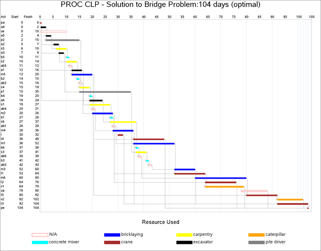
A Gantt chart of the schedule in Output 3.9.3, produced using the SAS/OR GANTT procedure, is displayed in Output 3.9.4. Each activity bar is color coded according to the resource associated with it. The legend identifies the name of the resource that is associated with each color.
Output 3.9.4: Gantt Chart for the Bridge Construction Project