| The CLP Procedure |
Example 1.1 Resource-Constrained Scheduling with Nonstandard Temporal Constraints
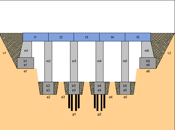
This example illustrates a real-life scheduling problem and is used as a benchmark problem in the CP community. The problem is to schedule the construction of a five-segment bridge (see Figure 1.1.1). It comes from a Ph.D. dissertation on scheduling problems (Bartusch; 1983).
The project consists of 44 tasks and a set of constraints relating these tasks. Table 1.6 displays the activity information, standard precedence constraints, and resource constraints. The sharing of a unary resource by multiple activities results in the resource constraints being disjunctive in nature.
Activity |
Description |
Duration |
Predecessors |
Resource |
|---|---|---|---|---|
pa |
beginning of project |
0 |
||
a1 |
excavation (abutment 1) |
4 |
pa |
excavator |
a2 |
excavation (pillar 1) |
2 |
pa |
excavator |
a3 |
excavation (pillar 2) |
2 |
pa |
excavator |
a4 |
excavation (pillar 3) |
2 |
pa |
excavator |
a5 |
excavation (pillar 4) |
2 |
pa |
excavator |
a6 |
excavation (abutment 2) |
5 |
pa |
excavator |
p1 |
foundation piles 2 |
20 |
a3 |
pile driver |
p2 |
foundation piles 3 |
13 |
a4 |
pile driver |
ue |
erection of temporary housing |
10 |
pa |
|
s1 |
formwork (abutment 1) |
8 |
a1 |
carpentry |
s2 |
formwork (pillar 1) |
4 |
a2 |
carpentry |
s3 |
formwork (pillar 2) |
4 |
p1 |
carpentry |
s4 |
formwork (pillar 3) |
4 |
p2 |
carpentry |
s5 |
formwork (pillar 4) |
4 |
a5 |
carpentry |
s6 |
formwork (abutment 2) |
10 |
a6 |
carpentry |
b1 |
concrete foundation (abutment 1) |
1 |
s1 |
concrete mixer |
b2 |
concrete foundation (pillar 1) |
1 |
s2 |
concrete mixer |
b3 |
concrete foundation (pillar 2) |
1 |
s3 |
concrete mixer |
b4 |
concrete foundation (pillar 3) |
1 |
s4 |
concrete mixer |
b5 |
concrete foundation (pillar 4) |
1 |
s5 |
concrete mixer |
b6 |
concrete foundation (abutment 2) |
1 |
s6 |
concrete mixer |
ab1 |
concrete setting time (abutment 1) |
1 |
b1 |
|
ab2 |
concrete setting time (pillar 1) |
1 |
b2 |
|
ab3 |
concrete setting time (pillar 2) |
1 |
b3 |
|
ab4 |
concrete setting time (pillar 3) |
1 |
b4 |
|
ab5 |
concrete setting time (pillar 4) |
1 |
b5 |
|
ab6 |
concrete setting time (abutment 2) |
1 |
b6 |
|
m1 |
masonry work (abutment 1) |
16 |
ab1 |
bricklaying |
m2 |
masonry work (pillar 1) |
8 |
ab2 |
bricklaying |
m3 |
masonry work (pillar 2) |
8 |
ab3 |
bricklaying |
m4 |
masonry work (pillar 3) |
8 |
ab4 |
bricklaying |
m5 |
masonry work (pillar 4) |
8 |
ab5 |
bricklaying |
m6 |
masonry work (abutment 2) |
20 |
ab6 |
bricklaying |
l |
delivery of the preformed bearers |
2 |
crane |
|
t1 |
positioning (preformed bearer 1) |
12 |
m1, m2, l |
crane |
t2 |
positioning (preformed bearer 2) |
12 |
m2, m3, l |
crane |
t3 |
positioning (preformed bearer 3) |
12 |
m3, m4, l |
crane |
t4 |
positioning (preformed bearer 4) |
12 |
m4, m5, l |
crane |
t5 |
positioning (preformed bearer 5) |
12 |
m5, m6, l |
crane |
ua |
removal of the temporary housing |
10 |
||
v1 |
filling 1 |
15 |
t1 |
caterpillar |
v2 |
filling 2 |
10 |
t5 |
caterpillar |
pe |
end of project |
0 |
t2, t3, t4, v1, v2, ua |
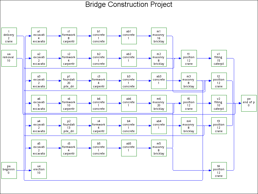
A network diagram illustrating the precedence constraints in this problem is shown in Output 1.1.2. Each node represents an activity and gives the activity code, truncated description, duration, and the required resource if any. The network diagram is generated using the NETDRAW procedure in SAS/OR software.
In addition to the standard precedence constraints, there are the following constraints:
The time between the completion of a particular formwork and the completion of its corresponding concrete foundation is at most four days.

There are at most three days between the end of a particular excavation (or foundation piles) and the beginning of the corresponding formwork.

and

The formworks must start at least six days after the beginning of the erection of the temporary housing.

The removal of the temporary housing can start at most two days before the end of the last masonry work.

The delivery of the preformed bearers occurs exactly 30 days after the beginning of the project.
The data set bridge defined by the SAS data set specification that follows, encapsulates all of the precedence constraints and also indicates the resources required by each activity. Note the use of the reserved variables _ACTIVITY_, _SUCCESSOR_, _LAG_, and _LAGDUR_ to define the activity and precedence relationships. The list of reserved variables can be found in Table 1.5. The _RESOURCE_ variable is not used by the CLP procedure directly but used separately in a preprocessing step to generate the RESOURCE statement for the CLP procedure.
   data bridge;
      format _ACTIVITY_ $32. _DESC_ $34. _RESOURCE_ $14.
             _SUCCESSOR_ $3. _LAG_ $3. ;
      input _ACTIVITY_ & _DESC_ & _DURATION_ _RESOURCE_ &
            _SUCCESSOR_ & _LAG_ & _LAGDUR_;
      datalines;
   a1   excavation (abutment 1)             4  excavator       s1   .     .
   a2   excavation (pillar 1)               2  excavator       s2   .     .
   a3   excavation (pillar 2)               2  excavator       p1   .     .
   a4   excavation (pillar 3)               2  excavator       p2   .     .
   a5   excavation (pillar 4)               2  excavator       s5   .     .
   a6   excavation (abutment 2)             5  excavator       s6   .     .
   ab1  concrete setting time (abutment 1)  1  .               m1   .     .
   ab2  concrete setting time (pillar 1)    1  .               m2   .     .
   ab3  concrete setting time (pillar 2)    1  .               m3   .     .
   ab4  concrete setting time (pillar 3)    1  .               m4   .     .
   ab5  concrete setting time (pillar 4)    1  .               m5   .     .
   ab6  concrete setting time (abutment 2)  1  .               m6   .     .
   b1   concrete foundation (abutment 1)    1  concrete_mixer  ab1  .     .
   b1   concrete foundation (abutment 1)    1  concrete_mixer  s1   ff   -4
   b2   concrete foundation (pillar 1)      1  concrete_mixer  ab2  .     .
   b2   concrete foundation (pillar 1)      1  concrete_mixer  s2   ff   -4
   b3   concrete foundation (pillar 2)      1  concrete_mixer  ab3  .     .
   b3   concrete foundation (pillar 2)      1  concrete_mixer  s3   ff   -4
   b4   concrete foundation (pillar 3)      1  concrete_mixer  ab4  .     .
   b4   concrete foundation (pillar 3)      1  concrete_mixer  s4   ff   -4
   b5   concrete foundation (pillar 4)      1  concrete_mixer  ab5  .     .
   b5   concrete foundation (pillar 4)      1  concrete_mixer  s5   ff   -4
   b6   concrete foundation (abutment 2)    1  concrete_mixer  ab6  .     .
   b6   concrete foundation (abutment 2)    1  concrete_mixer  s6   ff   -4
   l    delivery of the preformed bearers   2  crane           t1   .     .
   l    delivery of the preformed bearers   2  crane           t2   .     .
   l    delivery of the preformed bearers   2  crane           t3   .     .
   l    delivery of the preformed bearers   2  crane           t4   .     .
   l    delivery of the preformed bearers   2  crane           t5   .     .
   m1   masonry work (abutment 1)          16  bricklaying     t1   .     .
   m1   masonry work (abutment 1)          16  bricklaying     ua   fs   -2
   m2   masonry work (pillar 1)             8  bricklaying     t1   .     .
   m2   masonry work (pillar 1)             8  bricklaying     t2   .     .
   m2   masonry work (pillar 1)             8  bricklaying     ua   fs   -2
   m3   masonry work (pillar 2)             8  bricklaying     t2   .     .
   m3   masonry work (pillar 2)             8  bricklaying     t3   .     .
   m3   masonry work (pillar 2)             8  bricklaying     ua   fs   -2
   m4   masonry work (pillar 3)             8  bricklaying     t3   .     .
   m4   masonry work (pillar 3)             8  bricklaying     t4   .     .
   m4   masonry work (pillar 3)             8  bricklaying     ua   fs   -2
   m5   masonry work (pillar 4)             8  bricklaying     t4   .     .
   m5   masonry work (pillar 4)             8  bricklaying     t5   .     .
   m5   masonry work (pillar 4)             8  bricklaying     ua   fs   -2
   m6   masonry work (abutment 2)          20  bricklaying     t5   .     .
   m6   masonry work (abutment 2)          20  bricklaying     ua   fs   -2
   p1   foundation piles 2                 20  pile_driver     s3   .     .
   p2   foundation piles 3                 13  pile_driver     s4   .     .
   pa   beginning of project                0  .               a1   .     .
   pa   beginning of project                0  .               a2   .     .
   pa   beginning of project                0  .               a3   .     .
   pa   beginning of project                0  .               a4   .     .
   pa   beginning of project                0  .               a5   .     .
   pa   beginning of project                0  .               a6   .     .
   pa   beginning of project                0  .               l    fse  30
   pa   beginning of project                0  .               ue   .     .
   pe   end of project                      0  .               .    .     .
   s1   formwork (abutment 1)               8  carpentry       b1   .     .
   s1   formwork (abutment 1)               8  carpentry       a1   sf   -3
   s2   formwork (pillar 1)                 4  carpentry       b2   .     .
   s2   formwork (pillar 1)                 4  carpentry       a2   sf   -3
   s3   formwork (pillar 2)                 4  carpentry       b3   .     .
   s3   formwork (pillar 2)                 4  carpentry       p1   sf   -3
   s4   formwork (pillar 3)                 4  carpentry       b4   .     .
   s4   formwork (pillar 3)                 4  carpentry       p2   sf   -3
   s5   formwork (pillar 4)                 4  carpentry       b5   .     .
   s5   formwork (pillar 4)                 4  carpentry       a5   sf   -3
   s6   formwork (abutment 2)              10  carpentry       b6   .     .
   s6   formwork (abutment 2)              10  carpentry       a6   sf   -3
   t1   positioning (preformed bearer 1)   12  crane           v1   .     .
   t2   positioning (preformed bearer 2)   12  crane           pe   .     .
   t3   positioning (preformed bearer 3)   12  crane           pe   .     .
   t4   positioning (preformed bearer 4)   12  crane           pe   .     .
   t5   positioning (preformed bearer 5)   12  crane           v2   .     .
   ua   removal of the temporary housing   10  .               pe   .     .
   ue   erection of temporary housing      10  .               .    .     .
   ue   erection of temporary housing      10  .               s1   ss    6
   ue   erection of temporary housing      10  .               s2   ss    6
   ue   erection of temporary housing      10  .               s3   ss    6
   ue   erection of temporary housing      10  .               s4   ss    6
   ue   erection of temporary housing      10  .               s5   ss    6
   ue   erection of temporary housing      10  .               s6   ss    6
   v1   filling 1                          15  caterpillar     pe   .     .
   v2   filling 2                          10  caterpillar     pe   .     .
   ;
The CLP procedure is then invoked by using the following statements with the SCHEDDATA= option, which is required for scheduling problems.
   /* extract project descriptions */
   proc sql;
      create table desc as
      select distinct _ACTIVITY_ as ACTIVITY,
                      _DESC_ as DESCRIPTION,
                      _RESOURCE_ as RESOURCE from bridge;
   quit;

   /* generate the REQUIRES statement */
   data _null_;
      length reqspec $8192.;
      retain reqspec "";
      set desc end=final;
      if (RESOURCE ~= " ") then
         reqspec=
            trim(reqspec)||" "||trim(ACTIVITY)||"="||"("||trim(RESOURCE)||")";
      if final then
         call symput ('reqstmt', "REQUIRES"||reqspec);
   run;

   /* invoke PROC CLP */
   proc clp actdata=bridge
            scheddata=sched_ex1
            dm=4
            solns=1
            restarts = 10
            showprogress;
      schedule edgefinder actselect=rand finish=104;
      resource excavator pile_driver carpentry concrete_mixer
               bricklaying crane caterpillar;
      &reqstmt;
   run;
The edge-finder consistency algorithms are activated using the EDGEFINDER option in the SCHEDULE statement. The REQUIRES statement listing all the resources is generated via the macro variable reqstmt. The FINISH= option is specified to find a solution in 104 days, which also happens to be optimal.
The sched_ex1 data set contains the complete schedule as computed by the CLP procedure, including the activity start and finish times and the assignment of resources. Since there is a variable for each resource in this data set and an activity gets assigned to at most one resource, it is possible to represent this information more concisely by merging the sched_ex1 data set with the desc data set by using the following statements. The resulting merged data set is shown in Output 1.1.3.
   /* merge descriptions, prepare to output the schedule data set */
   proc sort data=sched_ex1;
      by ACTIVITY;
   run;
   data sched_ex1;
      merge desc sched_ex1;
      by ACTIVITY;
   run;
   proc sort data=sched_ex1;
      by START FINISH;
   run;
      /* display the schedule */
   proc print data=sched_ex1 noobs width=min;
      var ACTIVITY DESCRIPTION START FINISH RESOURCE;
      title 'Bridge Construction Schedule';
   run;
| Bridge Construction Schedule |
| ACTIVITY | DESCRIPTION | START | FINISH | RESOURCE |
|---|---|---|---|---|
| pa | beginning of project | 0 | 0 | |
| a4 | excavation (pillar 3) | 0 | 2 | excavator |
| ue | erection of temporary housing | 0 | 10 | |
| a5 | excavation (pillar 4) | 2 | 4 | excavator |
| p2 | foundation piles 3 | 2 | 15 | pile_driver |
| a1 | excavation (abutment 1) | 4 | 8 | excavator |
| s5 | formwork (pillar 4) | 6 | 10 | carpentry |
| a3 | excavation (pillar 2) | 8 | 10 | excavator |
| b5 | concrete foundation (pillar 4) | 10 | 11 | concrete_mixer |
| s1 | formwork (abutment 1) | 10 | 18 | carpentry |
| ab5 | concrete setting time (pillar 4) | 11 | 12 | |
| m5 | masonry work (pillar 4) | 12 | 20 | bricklaying |
| p1 | foundation piles 2 | 15 | 35 | pile_driver |
| a2 | excavation (pillar 1) | 17 | 19 | excavator |
| b1 | concrete foundation (abutment 1) | 18 | 19 | concrete_mixer |
| s4 | formwork (pillar 3) | 18 | 22 | carpentry |
| ab1 | concrete setting time (abutment 1) | 19 | 20 | |
| a6 | excavation (abutment 2) | 19 | 24 | excavator |
| m1 | masonry work (abutment 1) | 20 | 36 | bricklaying |
| b4 | concrete foundation (pillar 3) | 22 | 23 | concrete_mixer |
| s2 | formwork (pillar 1) | 22 | 26 | carpentry |
| ab4 | concrete setting time (pillar 3) | 23 | 24 | |
| b2 | concrete foundation (pillar 1) | 26 | 27 | concrete_mixer |
| s6 | formwork (abutment 2) | 26 | 36 | carpentry |
| ab2 | concrete setting time (pillar 1) | 27 | 28 | |
| l | delivery of the preformed bearers | 30 | 32 | crane |
| b6 | concrete foundation (abutment 2) | 36 | 37 | concrete_mixer |
| s3 | formwork (pillar 2) | 36 | 40 | carpentry |
| m2 | masonry work (pillar 1) | 36 | 44 | bricklaying |
| ab6 | concrete setting time (abutment 2) | 37 | 38 | |
| b3 | concrete foundation (pillar 2) | 40 | 41 | concrete_mixer |
| ab3 | concrete setting time (pillar 2) | 41 | 42 | |
| m4 | masonry work (pillar 3) | 44 | 52 | bricklaying |
| t1 | positioning (preformed bearer 1) | 44 | 56 | crane |
| m3 | masonry work (pillar 2) | 52 | 60 | bricklaying |
| t4 | positioning (preformed bearer 4) | 56 | 68 | crane |
| v1 | filling 1 | 56 | 71 | caterpillar |
| m6 | masonry work (abutment 2) | 60 | 80 | bricklaying |
| t2 | positioning (preformed bearer 2) | 68 | 80 | crane |
| ua | removal of the temporary housing | 78 | 88 | |
| t5 | positioning (preformed bearer 5) | 80 | 92 | crane |
| v2 | filling 2 | 92 | 102 | caterpillar |
| t3 | positioning (preformed bearer 3) | 92 | 104 | crane |
| pe | end of project | 104 | 104 |
A Gantt chart of the schedule in Output 1.1.3, produced using the GANTT procedure in SAS/OR software, is displayed in Output 1.1.4. Each activity bar is also color coded according to the resource associated with it. The legend identifies the name of the resource associated with each color.

Note: This procedure is experimental.
Copyright © 2008 by SAS Institute Inc., Cary, NC, USA. All rights reserved.