The NETDRAW Procedure
- Overview
- Getting Started
-
Syntax

-
DetailsNetwork Input Data SetVariables in the Network Data SetMissing ValuesLayout of the NetworkFormat of the DisplayPage FormatLayout Data SetControlling the LayoutTime-Scaled Network DiagramsZoned Network DiagramsOrganizational Charts or Tree DiagramsFull-Screen VersionGraphics VersionUsing the Annotate FacilityWeb-Enabled Network DiagramsMacro Variable _ORNETDRComputer Resource RequirementsODS Style Templates
-
ExamplesLine-Printer Network DiagramGraphics Version of PROC NETDRAWSpanning Multiple PagesThe COMPRESS and PCOMPRESS OptionsControlling the Display FormatNonstandard Precedence RelationshipsControlling the Arc-Routing AlgorithmPATTERN and SHOWSTATUS OptionsTime-Scaled Network DiagramFurther Time-Scale OptionsZoned Network DiagramSchematic DiagramsModifying Network LayoutSpecifying Node PositionsOrganizational Charts with PROC NETDRAWAnnotate Facility with PROC NETDRAWAOA Network Using the Annotate FacilityBranch and Bound TreesStatement and Option Cross-Reference Tables
- References
Page Format
Figure 9.8: Page Layout
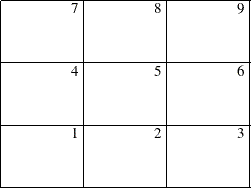
As explained in the section Format of the Display, if the network fits on one page, it is centered on the page (unless the NOVCENTER option is specified); otherwise, it is split onto different pages appropriately, and each page is drawn starting at the bottom left corner. If the network is drawn on multiple pages, the procedure numbers each page of the diagram on the top right corner of the page. The pages are numbered starting with the bottom left corner of the entire picture. Thus, if the network diagram is broken into three horizontal and three vertical levels and you want to paste all the pieces together to form one picture, they should be arranged as shown in Figure 9.8.
The number of pages of graphical output produced by the NETDRAW procedure depends on several options such as the NXNODES=, NYNODES=, HPAGES=, VPAGES=, COMPRESS, PCOMPRESS, HEIGHT=, and the ID= options. The value of the HTEXT= option and the number of variables specified in the ID= options determines the size of each node in the network diagram, which in turn affects the number of horizontal and vertical pages needed to draw the entire network. The number of pages is also affected by the global specification of the HPOS=, VPOS=, HSIZE=, and VSIZE= graphics options.
The COMPRESS and PCOMPRESS options force the entire network diagram to be drawn on a single page. You can explicitly control the number of horizontal and vertical pages using the HPAGES= and VPAGES= options. The NXNODES= and NYNODES= options enable you to specify the number of nodes in the horizontal and vertical directions, respectively, on each page of the network diagram.
For examples of these options and how they affect the network diagram output, see Example 9.5.