| The DTREE Procedure |
| Displaying the Decision Tree |
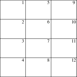
PROC DTREE draws the decision tree either in line-printer mode or in graphics mode. However, you need to have SAS/GRAPH software licensed at your site to use graphics mode. In many cases, the procedure draws the decision tree across page boundaries. If the decision tree diagram is drawn on multiple pages, the procedure numbers each page of the diagram on the upper right corner of the page (unless the NOPAGENUM option is specified). The pages are numbered starting with the upper left corner of the entire diagram. Thus, if the decision tree diagram is broken into three horizontal and four vertical levels and you want to paste all the pieces together to form one picture, they should be arranged as shown in Figure 7.10.
The number of pages that are produced depends on the size of the tree and on the number of print positions that are available in the horizontal and vertical directions. Table 7.28 lists all options you can use to control the number of pages.
Option |
Effect |
Amounts of information displayed on the diagram |
|
Maximum decimal width allowed (the precision) to format numerical values into |
|
Maximum field width allowed to format numerical values |
|
No labels are displayed on the diagram |
|
Maximum field width allowed to format outcome names |
|
Vertical spaces between two successive end nodes |
 format
 If the GRAPHICS option is used, the following options can be used to control the number of pages:
The COMPRESS option draws the entire decision tree on one page.
The HSYMBOL= option controls the height of all symbols.
The HTEXT= option controls the height of text in the tree.
The HEIGHT= option in a SYMBOL definition specifies the height of a symbol.
The HTEXT= option in a GOPTIONS statement specifies the height of all text.
The HTITLE= option in a GOPTIONS statement specifies the height of the first title line.
The HPOS= and VPOS= options in a GOPTIONS statement change the number of rows and columns.
Note that the font used for all text may also affect the number of pages needed. Some fonts take more space than others.
If the decision tree diagram is produced on a line printer, you can use the FORMCHAR= option to control the appearance the links and the junctions of the diagram. When the GRAPHICS options is specified, several options are available to enhance the appearance of the decision tree diagram. These are described in the section Graphics Options. In addition, there are many other options available in the GOPTIONS statement and the SYMBOL statement for controlling the details of graphics output. Refer to the relevant chapters in SAS/GRAPH Software: Reference for a detailed discussion of the GOPTIONS and SYMBOL statements.
Table 7.29, Table 7.30, and Table 7.31, show the relationship among the options for controlling the appearance of texts, nodes, and links, respectively. The order that PROC DTREE uses in determining which option is in effect is also provided.
For ODS purposes, the label of the decision tree diagram drawn in line-printer quality is "Treeplot."
Object |
Specification |
Search Order |
|
|---|---|---|---|
Text |
Font |
1. |
The FTEXT= option |
2. |
The FTEXT= option in a GOPTIONS statement |
||
3. |
The Font attribute of the GraphDataText element of the current ODS style definition (if the GSTYLE system option is active) |
||
4. |
Hardware font |
||
Color |
1. |
The CTEXT= option |
|
2. |
The CTEXT= option in a GOPTIONS statement |
||
3. |
The Color attribute of the GraphDataText element of the current ODS style definition (if the GSTYLE system option is active) |
||
4. |
The first color in the colors list |
||
Height |
1. |
The value of the HTEXT= option |
 times the value of the HTEXT= option
 in a GOPTIONS statement
  If this option is not specified, the default value 1 is used.
 The default value of this option is 1 unit.
Object |
Specification |
Search Order |
|
|---|---|---|---|
Chance |
Symbol |
1. |
The VSYMBOLC= option |
Nodes |
2. |
The VALUE= and FONT= options in the mth generated SYMBOL definition, if SYMBOLC=m is used |
|
3. |
The default symbol, CIRCLE |
||
Color |
1. |
The CSYMBOLC= option |
|
2. |
The CV= option in the mth generated SYMBOL definition, if SYMBOLC=m is used |
||
3. |
The CSYMBOL= option in a GOPTIONS statement |
||
4. |
The ContrastColor attribute of the GraphData1 element of the current ODS style definition (if the GSTYLE system option is active) |
||
5. |
The fifth color in the colors list |
||
Height |
1. |
h times the value of the HEIGHT= option in the mth generated SYMBOL definition, if both the HSYMBOL=h and the SYMBOLC=m are specified |
|
2. |
The HSYMBOL= option, if it is specified |
||
3. |
The HEIGHT= option in the mth generated symbol definition, if SYMBOLC=m is used |
||
4. |
The default value, |
||
Decision |
Symbol |
1. |
The VSYMBOLD= option |
Nodes |
2. |
The VALUE= and FONT= options in the dth generated SYMBOL definition, if SYMBOLD=d is used |
|
3. |
The default value, SQUARE |
||
Color |
1. |
The CSYMBOLD= option |
|
2. |
The CV= option in the dth generated SYMBOL definition, if SYMBOLD=d is used |
||
3. |
The CSYMBOL= option in a GOPTIONS statement |
||
4. |
The ContrastColor attribute of the GraphData5 element of the current ODS style definition (if the GSTYLE system option is active) |
||
5. |
The fourth color in the colors list |
||
Height |
1. |
h times the value of the HEIGHT= option in the dth generated SYMBOL definition, if both the HSYMBOL=h and the SYMBOLD=d are specified |
|
2. |
The HSYMBOL= option, if it is specified |
||
3. |
The HEIGHT= option in the dth generated symbol definition, if SYMBOLD=d is used |
||
4. |
The default value, |
||
End |
Symbol |
1. |
The VSYMBOLE= option |
Nodes |
2. |
The VALUE= and FONT= options in the nth generated SYMBOL definition, if SYMBOLE=n is used |
|
3. |
The default value, DOT |
||
Color |
1. |
The CSYMBOLE= option |
|
2. |
The CV= option in the nth generated SYMBOL definition if the option SYMBOLE=n is specified |
||
3. |
The CSYMBOL= option in a GOPTIONS statement |
||
4. |
The ContrastColor attribute of the GraphData8 element of the current ODS style definition (if the GSTYLE system option is active) |
||
5. |
The sixth color in the colors list |
||
Height |
1. |
h times the value of the HEIGHT= option in the nth generated SYMBOL definition, if both the HSYMBOL=h and the SYMBOLE=n are specified |
|
2. |
The HSYMBOL= option, if it is specified |
||
3. |
The HEIGHT= option in the nth generated symbol definition, if SYMBOLE=n is used |
||
4. |
The default value, |
 cell
cell
Object |
Specification |
Search Order |
|
|---|---|---|---|
Links |
Type |
1. |
The LSTYLE= option |
for |
2. |
The LINE= in the ith generated SYMBOL definition, |
|
Regular |
if LINKA=i is used |
||
Outcomes |
3. |
The default value, |
|
Color |
1. |
The CLINK= option |
|
2. |
The CI= option in the ith generated SYMBOL definition, if LINKA=i is used |
||
3. |
The ContrastColor attribute of the GraphData3 element of the current ODS style definition (if the GSTYLE system option is active) |
||
4. |
The third color in the colors list |
||
Thickness |
1. |
The LWIDTH= option |
|
2. |
The WIDTH= option in the ith generated SYMBOL definition, if LINKA=i is used |
||
3. |
The default value, |
||
Links |
Type |
1. |
The LSTYLEB= option |
for |
2. |
The LINE= in the jth generated SYMBOL definition, |
|
Optimal |
if LINKB=j is used |
||
Decision |
3. |
The default value, |
|
Color |
1. |
The CBEST= option |
|
2. |
The CI= option in the jth generated SYMBOL definition, if LINKB=j is used |
||
3. |
The ContrastColor attribute of the GraphData2 element of the current ODS style definition (if the GSTYLE system option is active) |
||
4. |
The second color in the colors list |
||
Thickness |
1. |
The LWIDTHB= option |
|
2. |
The WIDTH= option in the jth generated SYMBOL definition, if LINKB=j is used |
||
3. |
|
||
Links |
Type |
1. |
The LSTYLEC= option |
That |
2. |
The LINE= in the kth generated SYMBOL definition, |
|
Fall |
if LINKC=k is used |
||
Across |
3. |
The default value, |
|
Pages |
Color |
1. |
Depends on whether or not it represents an optimal decision |
Thickness |
1. |
Depends on whether or not it represents an optimal decision |
 times the thickness of links that represent regular outcomes
 Copyright © SAS Institute, Inc. All Rights Reserved.