DataFlux Data Management Studio 2.5: User Guide
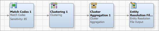
A simple data job using suggestion-based matching usually contains a Match Codes node, a Clustering node, and a Cluster Aggregation node, in addition to the input and output nodes. This configuration is acceptable when there is only one data type ("field") that generates match codes with scores.
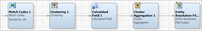
However, if match codes with scores are being generated from multiple fields, placing an additional Calculated Field node before the Cluster Aggregation node is recommended.
In the following discussion, outputs of each node will be shown using the same simple example data. In this example, a record contains two personal names: a child's name and a parent's name. Notice that record 0 differs from record 1 by one character insertion in the child's given name and one transposition in the family names.
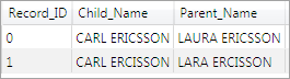
Example Input Records
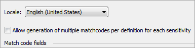
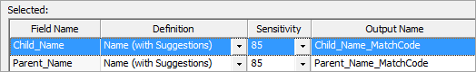
To effectively use a suggestion-based match definition in the Match Codes node, the definition must be selected for use on a field in the node's properties. In addition, the Allow generation of multiple match codes per definition for each sensitivity check box must be selected. Selecting this check box enables combination-based matching and/or suggestion-based matching, if present in the match definition.
![]() Note: The check box setting has no effect on match definitions that do not use either combination-based or suggestion-based matching.
Note: The check box setting has no effect on match definitions that do not use either combination-based or suggestion-based matching.
If the Allow generation of multiple match codes per definition for each sensitivity check box is selected, the Match Codes node will output an additional score field for each match code output field. These fields are created automatically and named XXX_Score, where XXX is the name of the match code output field. The score fields should be passed through any other nodes that follow the Match Codes node.
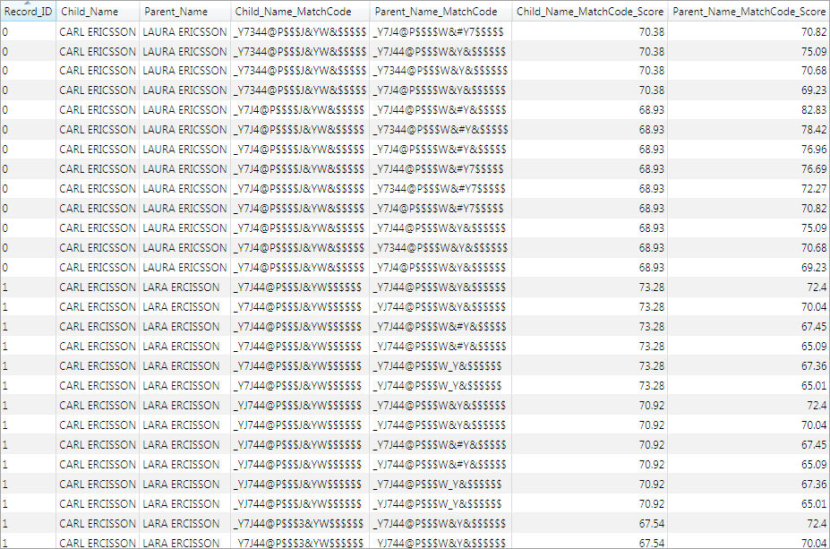
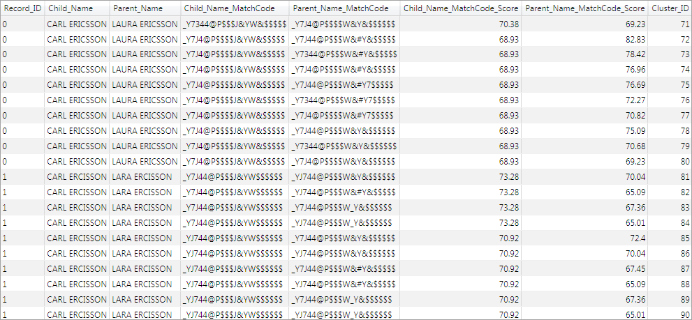
As shown in the preceding example, the Match Codes node has been set up to generate match codes on both the child's name and the parent's name. If the match definition outputs up to N match codes for the child's name (for example, "CARL ERICSSON") and up to N match codes for the parent's name (for example, "LAURA ERICSSON"), there could be up to N2 rows output for each record. Several rows of the match code output are shown in the following display.
No special actions need to be taken in the Clustering node when using suggestion-based matching, other than ensuring that the score fields are passed through to the next node through the Additional Outputs.
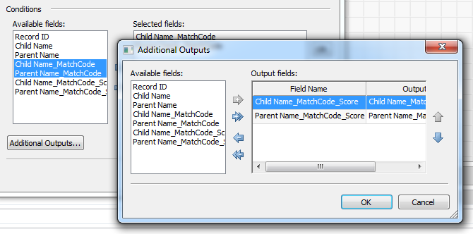
In the following example, the Clustering node is set up to cluster on both the match code for the child's name and the match code for the parent's name.

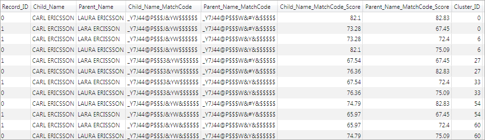
The output of the Clustering node (with multiple-record clusters only) is shown in the following display. Notice that both input records have been assigned to clusters 0, 6, 27, 33, 54, and 60.
There are also numerous single-record clusters, shown in the following display, that contain only either record 0 or record 1.
The Calculated Field node, available from the Utilities folder in the Nodes tree, enables several numeric fields to be mathematically combined together into a new field. In the Selected Fields grid, each field can have a weight assigned to it. For each record, the weighted values are combined into a new value using the selected Operation—for example, by taking the mean of the weighted values. The result is then placed into a new Output Field.
The Calculated Field node is a general-purpose utility node and has many applications in data jobs. When working with suggestion-based matching, it is used to combine the scores from several match code fields into a single score that will be passed to the next node and on to the entity resolution stage. The weight of each individual field in the combined score reflects how important the field is thought to be, relative to the other fields. While it is not strictly necessary to combine the scores in this way, it is often convenient to see a single numeric value for each record in a cluster.
The available choices for the Operation are:
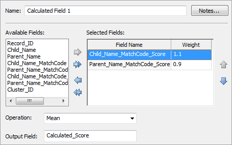
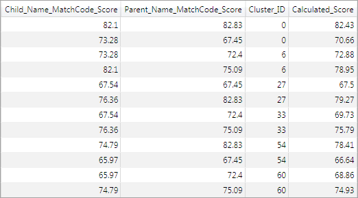
Because there are two match code fields, there are two score fields as well. In this scenario, the child's name is considered to be more important than the parent's name in computing the combined score, so the score for the match code generated from the child's name is weighted slightly higher. The following display shows several rows of the output (with multiple-record clusters only) when the Calculated Field node has been set up to combine the two scores into a new field using the Mean operation. Some columns are omitted for brevity.
The Cluster Aggregation node, available from the Entity Resolution folder in the Nodes tree, is used to combine several clusters that contain exactly the same set of records.
It is a common occurrence for two or more clusters to contain the same set of records, but with different scores for the match codes, as shown in the preceding example. The Cluster Aggregation node constructs one cluster from the set to represent all the clusters, and discards the other clusters.
While it is not strictly necessary to perform cluster aggregation, doing so is usually convenient because it frees you from having to examine and resolve multiple clusters with the same memberships during the entity resolution stage. The option to remove subclusters (see the following discussion) is also helpful in reducing the amount of information that must be examined.
The properties of the Cluster Aggregation node are shown in the following display. Using the specified Cluster ID Field, Primary Key Field, and Score Field, the scores are aggregated within each cluster using the selected Scoring Method and Scoring Algorithm. The possible choices for each scoring method and algorithm, together with their effects, are described in the following table.
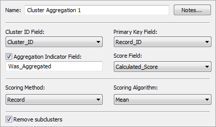
Clearly, aggregation will not be applied to clusters whose member records form a unique set, since there is no other cluster with which they could be aggregated. A visible indicator of which clusters are affected by aggregation is provided by the optional Aggregation Indicator Field.
Selecting the Remove subclusters check box causes any cluster that is a subset of another cluster to be silently suppressed from the output. Cluster A is a subset of cluster B if all the records in cluster A are also contained in cluster B, and cluster B is larger than cluster A.
| Scoring Method | Scoring Algorithm | Effect |
|---|---|---|
| Record | Maximum | Each record in the aggregated cluster has the mean score of that record over all the clusters. |
| Mean | Each record in the aggregated cluster has the maximum score of that record over all the clusters. | |
| Mean with scaling | Same as mean, but the scores are scaled to span the same range as the original scores. | |
| Median | Each record in the aggregated cluster has the median score of that record over all the clusters. | |
| Minimum | Each record in the aggregated cluster has the minimum score of that record over all the clusters. | |
| Cluster | Highest Maximum | The maximum value in each cluster is computed, and the cluster with the highest maximum is taken as the aggregated cluster. |
| Highest Mean | The mean value in each cluster is computed, and the cluster with the highest mean is taken as the aggregated cluster. | |
| Highest Minimum | The minimum value in each cluster is computed, and the cluster with the highest minimum is taken as the aggregated cluster. | |
| Lowest Maximum | The maximum value in each cluster is computed, and the cluster with the lowest maximum is taken as the aggregated cluster. | |
| Lowest Mean | The mean value in each cluster is computed, and the cluster with the lowest mean is taken as the aggregated cluster. | |
| Lowest Minimum | The minimum value in each cluster is computed, and the cluster with the lowest minimum is taken as the aggregated cluster. |
The complete output of the Cluster Aggregation node is shown in the following display. Notice that the six clusters that contain both records have been aggregated together into one cluster, cluster 0.

The single-record clusters, which each contain either only record 0 or only record 1, have been suppressed, because they are subclusters of cluster 0 and the Remove subclusters option was selected.
Notice that the large number of clusters obtained from the clustering node has now been reduced to 1. This reduces the amount of data displayed during the following entity resolution stage and simplifies the cluster resolution effort considerably.
If the Remove subclusters option had not been selected, there would be two additional aggregated clusters: one containing record 0 and another containing record 1, as shown in the following display. In this case, there would be three clusters remaining.

If match codes are being generated for entity resolution, the aggregated cluster output should be passed to an Entity Resolution File Output node. General usage of this node is discussed in Generating an Entity Resolution File.
No special actions need to be taken when using suggestion-based matching, except for setting the Confidence value field. This should be set to the field that contains the match code score (or the calculated score from the Calculated Field node, if more than one input field is generating match codes), as shown in the following display.
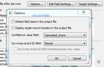
Note that if more than one field is generating match codes, those individual match code scores can still be passed to the entity resolution stage (for example, for informational purposes) by selecting them as output fields. Generating the calculated score and using it as the confidence value field simply provides a convenient single numeric value to represent the likelihood of a record's assignment to a certain cluster.
General usage of the entity resolution file is discussed in Working with an Entity Resolution File. When the file is generated using suggestion-based matching, the major difference from combination-based matching is that records can exist in multiple clusters. Clusters that have at least one record in common are called related clusters.
When working with suggestion-based clusters, the goals are therefore to:
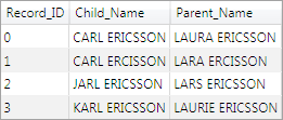
In the previous example, because there were only two records, the possible composition of clusters was naturally limited, and handling the aggregated result in the entity resolution stage would be a trivial task. A slightly more realistic example will now be shown, consisting of the records shown in the following display.
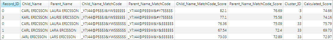
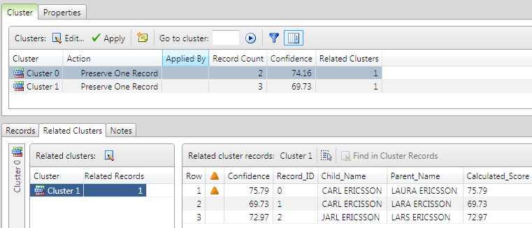
The input to the entity resolution file (after cluster aggregation) is shown in the following display. Notice that records 0 and 3 are in a cluster, while records 0, 1, and 2 are in another cluster. These two clusters are all that remain after the clusters with identical membership were aggregated and all subclusters were suppressed.
The following example shows that when the cluster with three records is selected in the cluster list, the other cluster with two records is shown as a related cluster. This is because both clusters share record 0. The records that are responsible for the relation between the clusters (in this case, only record 0) are marked with an  icon.
icon.
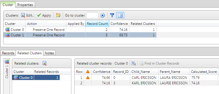
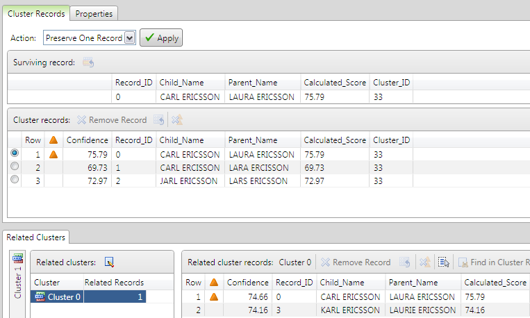
Similarly, the following example shows that when the cluster with two records is selected in the cluster list, the other cluster with three records is also shown, and shared record 0 is marked with an icon.
A judgment call is now needed to determine the cluster to which the shared record (record 0) should ultimately be assigned.
Notice that record 0 has a slightly higher score in the cluster with three records than in the cluster with two records. The difference is very small, but indicates that according to the rules of the match definition, record 0 is deemed slightly more likely to belong to the cluster in which it scores higher.
Assume that after examining the clusters, you decide that record 0 should belong to the cluster with three records rather than the cluster with two records (that is, that record 0 should be clustered with records 1 and 2, not with record 3). It is now necessary to remove record 0 from the cluster to which it should not belong.
Clusters can be edited by double-clicking the cluster name in the cluster list. The user interface for editing a cluster is shown in the following display.
To remove a highlighted record from a cluster in which it is contained, click the Remove Record  button on the toolbar. To retain the highlighted record in the selected cluster and remove it from all other related clusters, click the Remove Record from Related Clusters
  button. The same actions can also be accessed from the context menu.
After record 0 has been removed from the cluster containing record 3, that cluster becomes a single-record cluster. At this point, every record is in exactly one cluster. All that is required now is to determine the surviving records for each cluster. Any one of the records in the cluster can be assigned in its entirety as the surviving record, or individual fields can be chosen from among the records in the cluster. Alternatively, if none of the available alternatives is desired, text can be typed freely into any field, as shown in the following display.
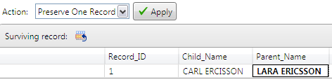
When you click Apply, the cluster is resolved using the selected Action. In this case, the surviving record will replace all the records in the cluster.
The amount of manual review effort expended at the entity resolution stage can often best be reduced by noticing common trends among records that are obviously incorrectly clustered, and suitably modifying the match definitions or job to help avoid these types of problems. For example, if there is a very common type of data entry error, factoring this knowledge into the match definition can improve the subjective quality of clustering. This will help limit the number of changes needed to assign the problematic records to the correct clusters.
Using the Cluster Aggregation node is strongly recommended. Selecting the Remove subclusters option in the properties for this node is also helpful. Using the Cluster Aggregation node greatly reduces the number of clusters that must be reviewed.
During the entity resolution stage, as a general guideline, reviewers should proceed as follows:
|
Documentation Feedback: yourturn@sas.com
|
Doc ID: dfDMStd_SBM_Data_Job.html |