Workflow Patterns
Overview
Only the most basic
processes can be represented as a single, sequential flow (Workflow
Pattern: Sequence). More realistic processes generally contain varying
combinations of activities based on business decisions derived from
the business data. These variations can be initiated by specific outcomes
from the previous task or by expression evaluation at decision points
to control the method of selecting a path through the process at run
time.
Defining Alternate Paths
Path Selection Based on Status
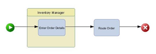
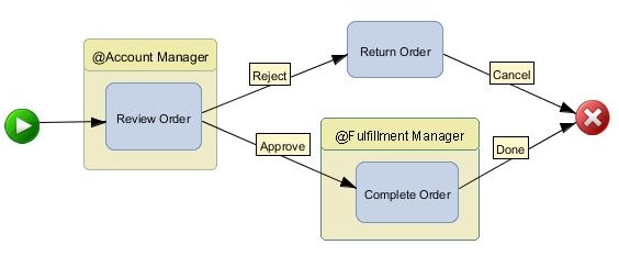
For example, assume
that you are defining a basic approval process with two possible outcomes:
approved or denied. You can define two status values: Approve and
Reject and then add the relevant status to the appropriate case in
the workflow by assigning it to the connection for that path. At run
time, the process continues to the next activity based on the status
corresponding to the action.
The status values are unique,
so there is only a single choice possible for this example (Workflow
Pattern: Exclusive Choice). SAS Workflow Studio also supports multiple
paths for the same status value (Workflow Pattern: Parallel). Using
multiple paths is similar to using a merge/fork gateway, which might
not have status assignments.
See Basic Workflow Examples for a detailed
example.
Note: Most SAS products that leverage
workflow use status values for every transition. Without status assignments,
the activity execution is controlled purely by sequence flow—the
order in which elements are connected—and gateways. SAS Workflow
Studio allows significant flexibility for defining process flow logic,
so process designers should carefully validate that the workflow behaves
as expected.
Path Selection Based on Expression Evaluation
In contrast to status
evaluation, decisions can be used to route the process flow by means
of evaluated expressions based on real-time business data values.
Decision gateways in SAS Workflow Studio contain Boolean expressions
that drive actions based on the calculated value. Thus, decision nodes
can be used to route process execution to one (Workflow Pattern: Exclusive
Choice) or more (Workflow Pattern: Inclusive Choice) of several alternate
outgoing paths, depending on the condition.

All expressions must
evaluate to a Boolean value and must conform to the Java language
syntax. In summary, each expression must comply with the following
rules:
See Decision Expression Examples for detailed
operator and function support and Boolean expression examples.
Tip
To use data objects when writing
Boolean expressions, press the F3 key to access a menu of valid data
objects for the current process.
Each expression corresponds
to a calculated value or outcome and is represented as a label in
a similar manner to status values. In addition to these user-defined
calculations, the special status of
Otherwise can
be assigned. Use this value to designate the logical path that should
be traversed when all defined expressions evaluate to false. In summary,
the Otherwise path represents the default
execution path when none of the expression values are true.
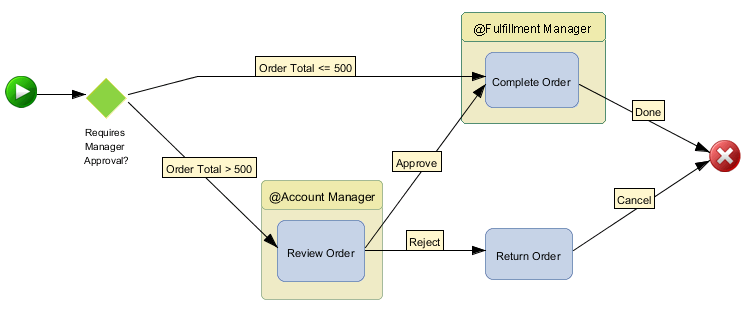
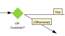
For the following example,
any order total that exceeds $500 requires manager approval before
it is fulfilled. The decision gateway is based on an Order Total data
object of type Number where the
Yes path
corresponds to a value exceeding the threshold and No,
where the order total is below the threshold, is approved automatically.
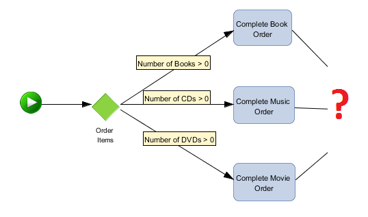
For a process flow where
one or more paths from a decision can be followed at the same time,
an inclusive choice decision might be used. For example, a mail order
company receives orders with combinations of items (books, music [CDs],
movies [DVDs]) with distinct fulfillment activities initiated for
each item type. A typical order contains quantities of more than one
product type.
Defining Parallel Paths
Overview
Frequently, processes
focus on sequences of activities where each task is activated upon
completion of the preceding task. At other times, a process might
require multiple tasks or process paths to execute in parallel after
a specific activity has completed. SAS Workflow Studio supports parallel
paths via the merge/fork gateway element.
Adding Merge/Fork Gateways

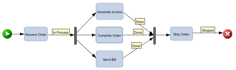
Here is an example of
a process flow that splits into three parallel activities (Generate
Invoice, Complete Order, Send Bill). The activities start only after
the Receive Order activity has completed.
See Basic Workflow Examples for a more
detailed parallel process example.
Note: Statuses cannot be assigned
to connections leading from a merge/fork gateway. All subsequent paths
are executed.
Tip
To change the orientation
of the merge/fork gateway from vertical to horizontal (and vice versa),
right-click the bar and then select Change orientation
option.
Defining Convergent Paths
Overview
In general, divergent
process flow logic eventually converges either by processing the inputs
as they are received (no synchronization) or by coordinating and consolidating
the inputs (synchronization) into a single execution path. These convergence
pattern types are detailed in the following sections.
Merging Paths without Synchronization
As a rule, alternate
paths should converge without synchronization to prevent deadlocks.
This means that exclusive choice decisions (exactly one path is selected)
should require only a single input upon convergence (Workflow Pattern:
Exclusive Merge). This can be accomplished in two ways:

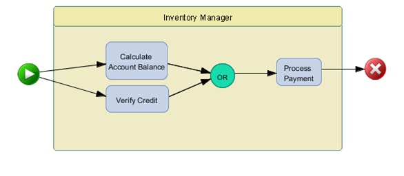
SAS Workflow Studio
currently supports logical XOR (exclusive) for the first option and
logical OR (inclusive) for the second option. So, for a single execution
of the convergent path, the logical OR gateway should be used. If
multiple executions are desired (one for each path), then the paths
should converge directly into an activity.

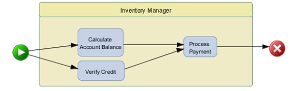
The following example
results in only a single work item (task instance) for Process Payment
after both Calculate Account Balance and Verify Credit have been completed.
However, any actions associated with the Process Payment activity
are executed twice.
Merging Paths with Synchronization
Finally, parallel execution
paths that require all tracks to complete should be joined and synchronized
before initiating the convergent path. This can be accomplished by
either using a merge/fork gateway or an AND-type logic gateway.
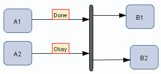
The parallel process
in Example of Parallel Processes illustrates
the use of a merge/fork gateway where the Ship Order task is not executed
until all three of the preceding tasks (Generate Invoice, Complete
Order, and Send Bill) complete. If more than
one activity exists after the gateway, then the activities are started
together and run independently. The following example shows a process
flow where a set of activities (B1, B2) starts only after another
set of activities (A1, A2) finishes:
Another variation on
the inclusive merge convergence pattern, which controls partial synchronization,
is sometimes referred to as the Discriminator model. This pattern
supports multiple inputs that trigger multiple executions, but not
necessarily one-to-one (selective execution). In other words, three
inputs might lead to the converged path, but there might be only two
trigger actions. The remaining input is ignored, if present. This
pattern is not supported by SAS Workflow Studio as an explicit gateway.
Additional Information on Workflow Patterns
For more information
on workflow patterns, see the Workflow Patterns Initiative Web site.
The following documents are of particular interest:
“Workflow Control-Flow Patterns: A Revised View.” 2006. Available http://www.workflowpatterns.com/documentation/documents/BPM-06-22.pdf.
“Workflow Patterns.” 2003. Available http://www.workflowpatterns.com/documentation/documents/wfs-pat-2002.pdf.