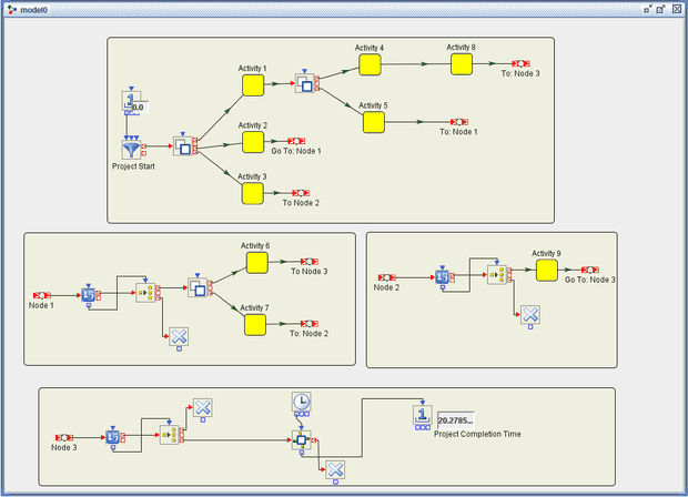
This example is a program evaluation and review technique (PERT) network model of a repair and retrofit project. All activity times are assumed to be triangularly distributed. The activities relate to power units, instrumentation, and a new assembly, and they involve standard types of operations.
At the beginning of the project, three parallel activities can be performed: the disassembly of power units and instrumentation (Activity 1), the installation of a new assembly (Activity 2), and the preparation for a retrofit check (Activity 3). Cleaning, inspecting, and repairing the power units (Activity 4) and calibrating the instrumentation (Activity 5) can be done only after the power units and instrumentation have been disassembled. Thus, Activities 4 and 5 must follow Activity 1 in the network. Following the installation of the new assembly (Activity 2) and after the instruments have been calibrated (Activity 5), a check of interfaces (Activity 6) and a check of the new assembly (Activity 7) can be made. The retrofit check (Activity 9) can be made after the assembly is checked (Activity 7) and the preparation for the retrofit check (Activity 3) has been completed. The assembly and test of power units (Activity 8) can be performed following the cleaning and maintenance of power units (Activity 4). The project is considered completed when all nine activities are completed. Since Activities 6, 8, and 9 require the other activities to precede them, their completion signifies the end of the project. The goal is to estimate the project completion time.
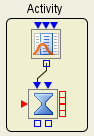
This model uses a common compound block (which consists of a Numeric Source block and a Delay block) to model the individual activities. Figure E.12 shows the structure of this compound block.
As was mentioned earlier, a triangular distribution is associated with each Numeric Source block. The distributional parameters for each of the activities are shown in Figure E.13.

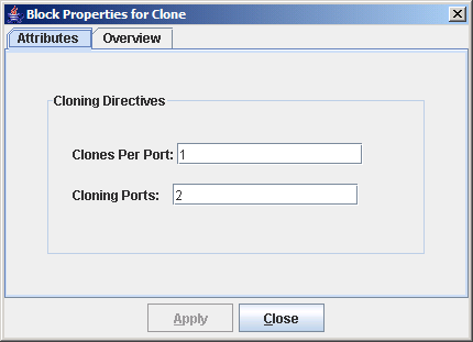
A Clone block is used to initiate parallel activities. When an entity enters a Clone block, the Clone block makes copies of the original entity and sends them out its various ports, depending on the cloning directives in Clone block. Figure E.14 shows the cloning directives for the first Clone block an entity encounters in this model. This Clone block has two additional output ports and sends one cloned entity out each port. This simulates the initiation of the disassembly of power units and instrumentation (Activity 1), the installation of a new assembly (Activity 2), and the preparation for a retrofit check (Activity 3) from the initial entity.
The combination of a Counter block with a Switch block is used in multiple places in the model. The Counter block simply counts how many entities have flowed through it and makes this count available via its OutCount port. Every time an entity enters a Switch block, the Switch block pulls the count value from its associated Counter block and then routes the entity accordingly. Each Switch block is essentially waiting until N entities have reached it (indicating completion of all preceding activities) before initiating the next activity in the model.
Each execution of the simulation model results in one estimate of how long it might take to complete the project. A large number of replications of the model execution are needed to produce enough data to construct a valid estimate for project completion time.