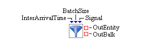
Ports represent the basic interface to blocks. Blocks usually have multiple ports. Depending on the functionality of the block, a block can have static ports (the same ports are always available for this type of block) or dynamic ports (ports can be dynamically created or deleted based on various properties of the block). An example of a block with static ports is the Entity Generator block used to create entities. (See Figure 4.2.) This block always has an InterArrivalTime, BatchSize, Signal, OutEntity, and OutBalk port.
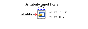
The Modifier block has static ports and optional dynamic ports. You use a Modifier block (Figure 4.3) to assign attributes to an entity that flows through a model. The number of ports available on the Modifier block is dependent on the number of attributes you have decided to set using that block. In Figure 4.3, three attributes are assigned using this Modifier block, so the block’s icon displays three dynamic attribute input ports along with the Modifier block’s standard static input and (two) output entity ports.
Blocks have two types of ports: value ports and entity ports. The ports are color-coded with value ports displayed in blue and entity ports in red. Value ports are always located on the top and bottom of the block icon, and entity ports are displayed on the right and left sides of the block icon. In general, values are data-oriented information such as numbers, character strings, observation objects, and data model objects, while entities represent special objects that flow through the model during a simulation, potentially carrying additional information or properties along with them.
Each value port can either be an input value port or an output value port. Similarly, entity ports can be input or output ports. An input port is used to get information into the block, and an output port is either used by the block to push information out or used by another block to pull information from the block. Input ports are drawn as triangles on the perimeter of a block, and output ports are represented by squares. In Figure 4.2, the InterArrivalTime port represents an input value port and the OutEntity port is an output entity port. When you first rest the pointer over a port, a tooltip with a brief label for the port appears. The ports for each block are described on the Overview tab in the block’s properties dialog box.
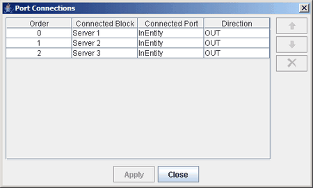
Each port has associated with it a Port Connections dialog box that is accessed by right-clicking the port. The Port Connections dialog box shows a list of all ports (and associated blocks) connected to the selected port. (See Figure 4.4.) The Order column in the dialog box indicates the priority of each port that is connected to the selected port. The order in which the ports appear in the dialog box is the order in which they are activated when the selected port needs to communicate with another port. The order can be changed by selecting a row in the Port Connections dialog box and then clicking the Up or Down arrow button to move the selected row in the list. Connections can also be deleted by selecting a row in the dialog box and clicking the Delete button located under the arrow buttons.