Priority-Based Preemption of Service
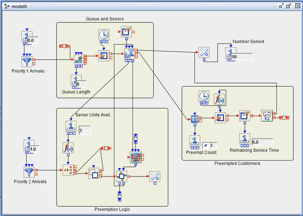
This example illustrates how to use several of the more advanced Simulation Studio blocks (Gate, Clone, Entity Group, Entity Filter) to model a system in which higher-priority customers can preempt lower-priority customers who are already receiving service. The preempted customers do not leave the system but instead wait for a server to become available again so that they can complete their service at a later time. Figure E.15 below depicts this model.
Figure E.15: Priority-Based Preemption Example

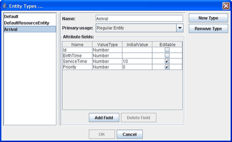
Entities are created by two distinct Entity Generator blocks—one for Priority 1 (lower priority) and one for Priority 2 (higher priority). Five Priority 1 entities are created (arrive) at time zero and five Priority 2 entities arrive one per time unit, starting at time 2. All entities are created from the entity type named Arrival, defined for this model with additional attributes ServiceTime and Priority, as shown in Figure E.16. ServiceTime for each entity is assigned a value of 10 units, and the Priority attribute is defined with a default value of 0 that is overwritten with 1 or 2 by the respective Entity Generator blocks.
Figure E.16: Entity Types Dialog Box for the Priority-Based Preemption Model

The entities enter a Queue block (Priority queueing policy) and await service from one of three servers. Priority 1 entities enter the Queue block immediately, but due to the fact that Priority 2 entities can preempt Priority 1 entities, their path (through the Preemption Logic section of the model) is more complex. A Priority 2 entity first enters a Switch block that receives input on available servers in the Server block (via output from the OutAvailable port on the Server block, fed through a Number Holder block for monitoring and then via a Formula block that evaluates whether the number of available servers is zero or positive). If a server is available, then the entity is routed to the Priority Queue block via a Connector; if no server is available, then the model must check to see whether a Priority 1 entity is currently in service that can be preempted.
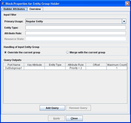
In this case, the Priority 2 entity is first sent through a Clone block, which creates an additional copy of the entity. The original entity is routed to the Priority Queue block via the Connector, awaiting possible preemption of a Priority 1 entity, while its clone is sent to a Gate block. The Gate block is designed to pull and push values each time an entity passes through it. In this case, the Gate block pushes a true value to the InUpate port of an Entity Group block, causing it to pull values to create a new entity group. This link is made via Connectors for visual simplicity. This Entity Group block is intended to identify one Priority 1 entity in service that can be preempted. It pulls values from the OutHoldings port of the Server block, which supplies data on entities currently in service, and selects one with Priority value less than 2, as shown in the properties dialog box in Figure E.17.
Figure E.17: Properties Dialog Box for Entity Group Block

This dialog box specifies that the group be created from entities with a Priority value less than 2 (here, that is equivalent to Priority=1) and that the group has a maximum count of 1. Thus the Entity Group block either identifies a single Priority 1 entity currently in service that can be preempted or finds that none exists. In either case, it sends its entity group (with either one member or none) back to the Gate block via a connection between the OutSubgroup1 port of the Entity Group block and the InServiceIn port of the Gate block. The Gate block then sends the entity group out its InServiceOut port to the InPreempt port of the Server block, effectively telling the Server block which in-service entity (if any) it should preempt.
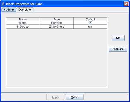
The InServiceIn and InServiceOut ports on the Gate block are created by defining an attribute InService for the Gate block with type Entity Group; the SignalIn and SignalOut ports are created similarly by defining a Boolean attribute Signal. The SignalIn port is not needed in this model. The properties dialog box for the Gate block is shown in Figure E.18. Note that the checked box in the Default column for Signal indicates that its value is true by default—needed in order to signal the Entity Group block to attempt to find a Priority 1 entity to preempt.
Figure E.18: Defining InService and Signal Attributes for the Gate Block

When a Priority 1 entity is preempted from the server, it is sent via the OutPreempt port on the server to a Count block (in the Preempted Customers Compound block) and then to a Modifier block where the remaining service time is computed. Before an entity enters the Server block, the current time is saved in the attribute EnterServTime. If an entity is preempted from service, the EnterServTime attribute is used by a Formula block to compute the remaining service time, as shown in Figure XX. The preempted entity is then routed to an Entity Filter block where the value of the attribute ServiceTime is checked. If the remaining ServiceTime is greater than 0, the preempted entity is routed back to the queue. If the remaining ServiceTime equals 0, the entity is routed to the Disposer block and leaves the system.