Modeling Assembly Operation and Parts Inventory System
This example shows how regular entities and resource entities, along with both standard and resource-oriented Simulation Studio blocks, can be used to model an assembly system and an associated parts inventory system. Each order (subassembly) arrives with a need for a given number of each of two parts. The parts needed are withdrawn from inventory and the assembly operation is executed; the completed order leaves the system. The part inventories are checked and replenished on a periodic basis. If the needed parts for an order are not immediately available, then the order must await inventory replenishment before it can proceed to the assembly operation. The model of this system is shown in Figure E.21.
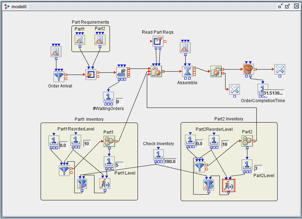
Entities that represent orders are created by the Entity Generator block labeled Order Arrival. Next, a Modifier block creates attributes NumPart1 and NumPart2, which correspond to the quantities of Part1 and Part2 needed, for each order, drawing values from the Numeric Source blocks in the Part Requirements compound block. The order then proceeds to a Queue block (FIFO policy) where it waits until its needed parts are available. The length of the queue is monitored.
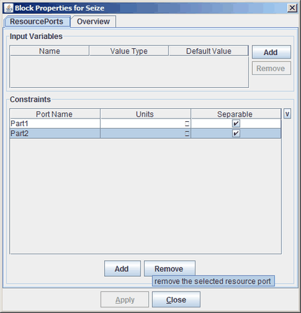
Following the Queue block is a Seize block that executes the procurement of needed parts. For this Seize block two resource ports, Part1 and Part2, were created as shown in the properties dialog box in Figure E.22. Each defined resource port for a Seize block creates a resource entity input port through which units of the corresponding resource entity enter the Seize block and are given to the requesting entity (the order). Because the Units column for each port is left blank, additional input ports called Part1_units and Part2_units are created so that the Seize block can pull the needed units of each resource for the current requesting entity. In this model, an Extractor block supplies the values of the NumPart1 and NumPart2 attributes to be used for the number of units for Part1 and Part2, respectively.
The order proceeds next to a Delay block that models the time needed for assembly (distributed uniformly between 30 and 60). Once assembly is complete, a Release block releases the previously seized units of the resource entities Part1 and Part2. In this case, since the parts are consumed during the assembly operation, they are routed to a Disposer block upon release. If the resource entities represented nondisposable resources, then they would be routed back to their respective resource pools or elsewhere in the model upon release.
Finally, the order proceeds to a Bucket block, which records the current age (time in the model) of each entity and (via a connection to the Bucket block’s OutLatestAge port) passes the information to a Number Holder block for reporting and possible data collection. The order entity then exits the system via a Disposer block.
In the lower half of the model are two areas (expanded compound blocks) labeled Part1 Inventory and Part 2 Inventory. These sections of the model simulate inventory management and replenishment for the two parts. The functionality for both parts is identical; so this example focuses on Part1. Inventory is checked every 180 time units and, if the inventory of Part1 is below the Part1 reorder level, an order equal to the Part1 reorder level is placed.
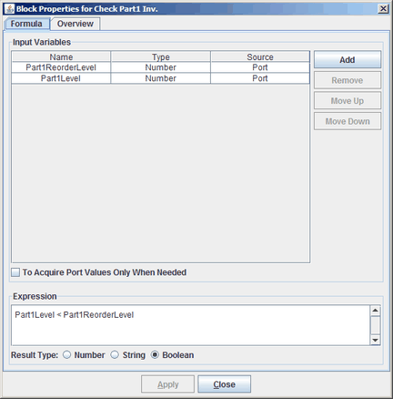
In order to simulate this inventory policy, a Number Holder block supplies a constant value of 180 as the InterValue Time for a Value Generator block. Thus, every 180 time units the Value Generator block pulls a Boolean value through its InValue port from a Formula Block that compares the current Part1 inventory level to its reorder level. The formula produces a true value (indicating the need for inventory replenishment) if inventory is under the reorder level and a false value otherwise. The details are shown in the properties dialog box for the Formula Block in Figure E.23.
This Boolean value flows out the OutValue port of the Value Generator block to the Signal input port of an Entity Generator block that represents inventory replenishment; if the value is true, it signals the Entity Generator block to produce entities according to its configuration—to replenish the Part1 inventory. The BatchSize input port of the Entity Generator is connected to the Number Holder block that holds the reorder level (10) for Part1, and the InterArrivalTime input port is attached to a Number Holder block that holds the value zero. Collectively, this means that upon receiving a true value from the Value Generator block, the Entity Generator block creates 10 Part1 resource entities immediately, sending them to the Part1 Resource Pool block. This completes the inventory replenishment operation, and all units of Part1 are available to be given to requesting order entities via the Seize block.
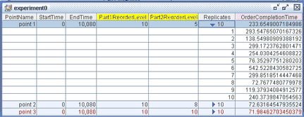
The reorder levels for Part1 and Part2 are declared as factors, and the order completion time is declared as a response; these factors and responses are included in the Experiment window. Three design points, with varying reorder levels for Part1 and Part2, are run for 10,080 time units, equal to one week if each time unit corresponds to one minute. Details about creating factors and responses and including them in the Experiment window are provided in Appendix C, Design of Experiments.
Each design point is run for ten replications and the results are recorded. The Experiment window for this model is shown in Figure E.24. The first design point is expanded to show all ten replications.