The BOM Procedure
- Overview
- Getting Started
-
Syntax

-
Details
-
Examples
Bill of Material with Single Input Data Set Bill of Material with Lead Time Information Bill of Material with Scrap Factor Information Planning Bill of Material Modular Bill of Material Bill of Material with Repeated Relationships Bill of Material Verification Roll-Up Cost in Indented Bill of Material Bill of Material Explosion Aggregating Forecasts Using PROC BOM Statement and Option Cross-Reference Tables
- References
Example 3.2 Bill of Material with Lead Time Information
As in Example 3.1, this example also uses a single input data set with each observation containing product structure data and part master data. Unlike the SlBOM1 data set (shown in Output 3.1.1) in which each observation contains three product structure records, each observation in the input data set SlBOM2, as depicted in Output 3.2.1, contains only one product structure record. The observations in both input data sets also contain one part master record. However, in the previous example, the variable Parent contains the part number for the part master record, whereas in the current example, the part number for the part master record is contained in the variable Component. In addition, in this example, each part master record also contains requirement (contained in the Gros_Req variable) and quantity on hand (contained in the On_Hand variable) information.
| ABC Lamp Company |
| PROC BOM Input Data Set |
| Parent | Component | Desc | Unit | LeadTime | QtyPer | Gros_Req | On_Hand |
|---|---|---|---|---|---|---|---|
| LA01 | Lamp LA | Each | 2 | . | 50 | 20 | |
| LA01 | B100 | Base assembly | Each | 1 | 1 | . | 50 |
| LA01 | S100 | Black shade | Each | 2 | 1 | . | . |
| LA01 | A100 | Socket assembly | Each | 1 | 1 | . | . |
| B100 | 1100 | Finished shaft | Each | 2 | 1 | . | . |
| B100 | 1200 | 6-Diameter steel plate | Each | 3 | 1 | . | . |
| B100 | 1300 | Hub | Each | 2 | 1 | . | . |
| B100 | 1400 | 1/4-20 Screw | Each | 1 | 4 | . | . |
| A100 | 1500 | Steel holder | Each | 2 | 1 | . | . |
| A100 | 1600 | One-way socket | Each | 2 | 1 | . | . |
| A100 | 1700 | Wiring assembly | Each | 1 | 1 | . | . |
| 1100 | 2100 | 3/8 Steel tubing | Inches | 3 | 26 | . | . |
| 1500 | 1400 | 1/4-20 Screw | Each | 1 | 2 | . | . |
| 1700 | 2200 | 16-Gauge lamp cord | Feet | 2 | 12 | . | . |
| 1700 | 2300 | Standard plug terminal | Each | 1 | 1 | . | . |
The following code produces the Indented BOM data set and the Summarized Parts data set. The Indented BOM data set, IndBOM2, is displayed in Output 3.2.2. The "PART=Component" specification in the STRUCTURE statement indicates that the Component variable contains the part number for the part master record in each observation. Since the LEADTIME= option is specified, a new variable, Tot_Lead, has been added to the Indented BOM data set. This variable denotes the total lead time accumulated from the root record (the top-most record) to the record identified by the value of the Part_ID variable.
  /* Create the indented BOM and the summarized parts list */
proc bom data=SlBOM2 out=IndBOM2 summaryout=SumBOM2;
   structure / part=Component
               leadtime=LeadTime
               parent=Parent
               component=Component
               quantity=QtyPer
               qtyonhand=On_hand
               requirement=Gros_Req
               id=(Desc Unit);
run;
| ABC Lamp Company |
| Indented Bill of Material, Part LA01 |
| _Level_ | _Parent_ | _Part_ | Desc | QtyPer | Qty_Prod | Unit | LeadTime | Tot_Lead | _Prod_ |
|---|---|---|---|---|---|---|---|---|---|
| 0 | LA01 | Lamp LA | . | 1 | Each | 2 | 2 | LA01 | |
| 1 | LA01 | B100 | Base assembly | 1 | 1 | Each | 1 | 3 | LA01 |
| 2 | B100 | 1100 | Finished shaft | 1 | 1 | Each | 2 | 5 | LA01 |
| 3 | 1100 | 2100 | 3/8 Steel tubing | 26 | 26 | Inches | 3 | 8 | LA01 |
| 2 | B100 | 1200 | 6-Diameter steel plate | 1 | 1 | Each | 3 | 6 | LA01 |
| 2 | B100 | 1300 | Hub | 1 | 1 | Each | 2 | 5 | LA01 |
| 2 | B100 | 1400 | 1/4-20 Screw | 4 | 4 | Each | 1 | 4 | LA01 |
| 1 | LA01 | S100 | Black shade | 1 | 1 | Each | 2 | 4 | LA01 |
| 1 | LA01 | A100 | Socket assembly | 1 | 1 | Each | 1 | 3 | LA01 |
| 2 | A100 | 1500 | Steel holder | 1 | 1 | Each | 2 | 5 | LA01 |
| 3 | 1500 | 1400 | 1/4-20 Screw | 2 | 2 | Each | 1 | 6 | LA01 |
| 2 | A100 | 1600 | One-way socket | 1 | 1 | Each | 2 | 5 | LA01 |
| 2 | A100 | 1700 | Wiring assembly | 1 | 1 | Each | 1 | 4 | LA01 |
| 3 | 1700 | 2200 | 16-Gauge lamp cord | 12 | 12 | Feet | 2 | 6 | LA01 |
| 3 | 1700 | 2300 | Standard plug terminal | 1 | 1 | Each | 1 | 5 | LA01 |
| ABC Lamp Company |
| Summarized Parts List, Period 2 |
| _Part_ | Low_Code | Gros_Req | On_Hand | Net_Req | LeadTime | Desc | Unit |
|---|---|---|---|---|---|---|---|
| 1100 | 2 | 0 | 0 | 0 | 2 | Finished shaft | Each |
| 1200 | 2 | 0 | 0 | 0 | 3 | 6-Diameter steel plate | Each |
| 1300 | 2 | 0 | 0 | 0 | 2 | Hub | Each |
| 1400 | 3 | 60 | 0 | 60 | 1 | 1/4-20 Screw | Each |
| 1500 | 2 | 30 | 0 | 30 | 2 | Steel holder | Each |
| 1600 | 2 | 30 | 0 | 30 | 2 | One-way socket | Each |
| 1700 | 2 | 30 | 0 | 30 | 1 | Wiring assembly | Each |
| 2100 | 3 | 0 | 0 | 0 | 3 | 3/8 Steel tubing | Inches |
| 2200 | 3 | 360 | 0 | 360 | 2 | 16-Gauge lamp cord | Feet |
| 2300 | 3 | 30 | 0 | 30 | 1 | Standard plug terminal | Each |
| A100 | 1 | 30 | 0 | 30 | 1 | Socket assembly | Each |
| B100 | 1 | 30 | 50 | 0 | 1 | Base assembly | Each |
| LA01 | 0 | 50 | 20 | 30 | 2 | Lamp LA | Each |
| S100 | 1 | 30 | 0 | 30 | 2 | Black shade | Each |
The data set SumBOM2 displayed in Output 3.2.3 contains the sorted summarized parts list for the production plan, in which 50 units of 'Lamp LA' are planned (say, in period 2). Based on the input data, 'Lamp LA' has 20 units and 'Base assembly' has 50 units currently on hand. The gross requirements of 30 units for 'B100', 'S100', and 'A100' are from the net requirement of 'LA01' (computed as Gros_Req  On_Hand). Since item 'B100' has 50 units on hand, which is more than its gross requirement, the net requirement of this item is 0. This implies that the gross requirements for '1100', '1200', and '1300' (components of the item 'B100') are all 0. However, the gross requirement for item '1400', which is also a component of 'B100', is not 0 but 60. This is due to the fact that item '1400' is also used in item '1500'.
The following code uses the Indented BOM data set produced in the previous invocation of PROC BOM to create a data set that can be used by the NETDRAW procedure.
     /* Prepare the data set for running NETDRAW */
   data IndBOM2a(drop=Part_ID);
      set IndBOM2;
      Paren_ID=Part_ID;
   run;

   data IndBOM2b;
      set IndBOM2(keep=Paren_ID Part_ID);
   run;

   data TreBOM2;
      set IndBOM2a IndBOM2b;
      LTnQP = put(LeadTime, f3.)||"  "||put(QtyPer, f3.);
   run;
PROC NETDRAW is invoked with the NODISPLAY option to create a data set (Layout2) that contains all the layout information for the tree structure. The OUT= option specifies the name of the layout data set:
/* Specify graphics options */
title h=4pct j=c 'Multilevel Bill of Material with Lead-time Offsetting';
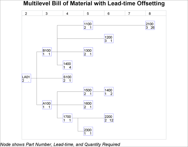
footnote h=3pct j=l
'Node shows Part Number, Lead-time, and Quantity Required';
pattern1 v=e c=blue;
/* Get the layout information for the BOM tree */
proc netdraw data=TreBOM2( where=(Paren_ID NE .) )
out=Layout2 nodisplay;
actnet / act=Paren_ID succ=Part_ID id=(_Part_ LTnQP Tot_Lead)
ybetween=3 xbetween=15 tree
rectilinear nodefid nolabel;
run;
In the next invocation, PROC NETDRAW uses a modified layout of the nodes to produce a diagram where the nodes are aligned according to the total lead time. The resulting tree diagram is shown in Output 3.2.4. Refer to
Chapter 9,
The NETDRAW Procedure
(SAS/OR User's Guide: Project Management), for details about the NETDRAW procedure.
  /* Lead time offset the X coordinate of each node */
data TreBOM2a;
   set Layout2;
   if _seq_ = 0;
   drop _seq_;
   _x_ = Tot_Lead;
run;
  /* Display the BOM tree with lead-time offsetting */
proc netdraw data=TreBOM2a out=NetOUT;;
   actnet / id=(_Part_ LTnQP)
            ctext=black htext=3 carcs=black
            align=Tot_Lead frame pcompress
            xbetween=15 ybetween=3
            arrowhead=0 rectilinear nodefid nolabel;
run;