Working with MXG Code to Stage Data
About MXG Adapters
Raw data sources that
are supported through MXG, such as z/OS data sources, might require
that you customize some of the MXG code. These changes might be required
in order to stage the data appropriately for the MXG adapters that
SAS IT Resource Management provides. SAS IT Resource Management supports
the following MXG adapters:
MXG Views
MXG views are
SQL views that are created automatically by the staging transformations
for MXG adapters.
MXG views are also created
by the Aggregation transformation for simple aggregations that are
based on staged tables from the same adapters in the preceding list.
One MXG view is created for each of these staged tables and simple
aggregation tables. The MXG views are stored in the same SAS library
in which their dependent SAS tables are stored.
IMACWORK and RMFINTRV Customizations Relevant to the RMF Domain Category of the SMF Adapter
The IMACWORK and RMFINTRV
members define the service classes (for those running in goal mode)
or performance groups (for those not running in goal mode) that make
up the workloads at your site. As with all MXG customizations, copy
the member that you want to modify from MXG.SRCLIB to MXGUSER.SRCLIB.
Edit these copies according to the instructions or comments therein.
Both members contain important notes about the mixing of service classes
with reporting classes (in goal mode) and control performance groups
with report performance groups (not in goal mode). A good job of customizing
these members ensures useful information in the XRMFWKL, XRMFWKP,
and XRMFINT tables.
Notice that the RMFINTRV
member permits the specification of more workloads than the IMACWORK
member permits by itself. Depending on your requirements, you could
edit just one, or both, of these members.
If you want to simultaneously
process SMF data from multiple machines and if these machines have
defined different RMF intervals, then you must also review the setting
of the
INTERVAL= macro parameter of the %VMXGRMFI
macro in the RMFINTRV member. The value that you choose for this parameter
must be an interval into which all RMF intervals that are being processed
divide evenly, without a remainder. For example, if the RMF intervals
of two machines are 10 minutes and 15 minutes, use INTERVAL=HALFHOUR. Review the comments in the RMFINTRV member for all possible values
for INTERVAL=. Even if you choose to process
the data from different machines in different executions of the same
staging job, subsequent analysis of the data is more effective if
both sets of the data are processed with the same value for the INTERVAL= parameter.
IMACSHFT Customizations Relevant to All Domain Categories of the SMF Adapter
The IMACSHFT member
is used to define your shift patterns. However, the SHIFT variable
in the IT Resource Management staged tables is populated from a formula
that is supplied with IT Resource Management, and is not propagated
from MXG. The IT Resource Management shift formula’s definition
can be changed to any valid SAS expression, or set of DATASTEP statements.
Customizations Relevant to the Jobs Domain Category of the SMF Adapter
IMACSPIN Customizations
IMACINTV Customizations
To enable the collection
of SMF interval data, you must first ensure that your system is configured
to generate the SMF interval accounting records. Work with your systems
programming team to determine the changes that might be required in
MVS system data set, SYS1.PARMLIB(SMFPRMxx) .
When that change is
made, you must also modify the IMACINTV MXG member. The default is set so that no TYPE30_V (SMF interval accounting) records
are written to SAS data sets. You must copy IMACINTV from MXG.SRCLIB to MXGUSER.SRCLIB and remove the comments from around the OUTPUT statement,
as described in the comments in the member.
Customizations Relevant to the CICS and DB2 Domain Categories of the SMF Adapter
IMACEXCL and UTILEXCL Customizations
The IMACEXCL member
contains the original methods by which modifications to the CICS SMF
type 110 record were supported in the MXG code that read them. These
original methods have been superseded by the UTILEXCL member. The
UTILEXCL member is the preferred method to dynamically create a new
IMACEXCL member that is customized to support the actual SMF data
being used at your site. The code is designed to run once, to generate
the IMACEXCL member. You must then store that member in MXGUSER.SRCLIB to enable the SMF records to
be decoded correctly into the SAS data sets.
ASUMCICX Customizations
SAS IT Resource Management
has added response time counters to the summarized CICS table that
MXG generates by default. To implement this feature, copy the ASUMCICX
member from the ITRM.CPMISC pds to your MXGUSER.SRCLIB. Failure to do this causes warning messages to be issued about missing
variables.
Note: SAS IT Resource Management
is adapted to include the new metrics that the ASUMCICX member creates.
This MXG member is stored in the SAS IT Resource Management CPMISC
PDS on z/OS , or the
misc folder on
UNIX, or the sasmisc folder on Windows.
Before you use the ASUMCICX member, you must run the UTILEXCL MXG
job. This job creates and implements the IMACEXCL member that is customized
for your site. Documentation for ASUMCICX and UTILEXCL can be found
inside each member.
IMACUOW Customizations
By default, no ASUMUOW
observations (or records) are written to the SAS data set. To process
unit-of-work data, you must modify the IMACUOW
MXG member. Copy it to your MXGUSER.SRCLIB and comment out (or delete)
the first definition of the two macros, _NOOBS and _YESOBS. Then remove
the comment indicator from the second definition, so that the macros
are defined as follows:
MACRO _NOOBS   %
MACRO _YESOBS  %
In addition, if you have MQ series data that you want to add to the CICS and DB2 unit-of-work process, modify the code as instructed in IMACUOW to remove the comment indicator from the following statement:
%LET MXGMQADD=YES;
IMACUOWT Customizations
By default, no ASUMUOWT
observations (or records) are written to the SAS data set. To process
unit-of-work data from ASG TMON for CICS and SMF DB2, you must modify
the IMACUOWT MXG member. Copy it to your MXGUSER.SRCLIB and comment out (or delete) the first definition of
the two macros, _NOOBS and _YESOBS. Then remove the comment indicator
from the second definition, so that the macros are defined as follows:
MACRO _NOOBS   %
MACRO _YESOBS  %
Customizations Relevant to the Jobs Domain Category of the CA TMS Adapter
By default, there is
no single DATETIME variable that represents the date and time of each
observation. Copy members IMACTMS5 and EXTMSDSN to your MXGUSER.SRCLIB . In the IMACTMS5 member, add
the variable DATETIME to both the _KTMSDSN and _KTMSTMS macros by
using the following code:
MACRO _KTMSDSN DATETIME %
MACRO _KTMSTMS DATETIME %
Customizations Relevant to the ASG TMON2CIC Adapter
Specify Spin Libraries for ASG TMON2CIC and IBM SMF
The ASG TMON2CIC and
IBM SMF adapters require that you specify a spin library for spin
data. The staging transformations for these adapters create and register
a separate spin library. Any existing data is moved to the new spin
library as part of the installation, update, or migration process.
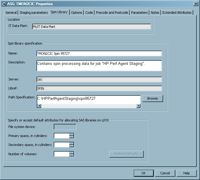
For the ASG TMON2CIC
and IBM SMF adapters, a spin library must be created. You can create
this library on the Spin Library tab of the
staging transformation properties. On this tab, you can specify various
parameters of the spin library or accept the default values. The spin
library is then created only after you open the Spin Library tab and select OK. (If you are using the Adapter Setup wizard to specify the ASG TMON2CIC and
IBM SMF adapter, the wizard creates the spin library for you.)
-
Specify the Name and Description of the spin library. SAS IT Resource Management generates default values for these parameters that include a standard naming convention for the library name (<adapter name> + Spin + <unique number>). For best results, if you modify the library name, use a standard naming convention that implements unique, identifiable names for all spin libraries that you register. A name value is required and a description is optional.
-
Enter the value for the Path Specification field for the metadata path that stores the spin library. SAS IT Resource Management generates the default path <adapter name> + Spin + <unique number>. You can accept the default path, enter a new path, or click Browse to select a path. A value is required in this field.Note: Browse is disabled when the selected application server is running on a machine using the
z/OS z/OS path manually, you can use either a prefix for a traditionalz/OS MY.DATAMART) or a root directory in the UFS hierarchical file system (/u/myname/datamart).
Limit IBM SMF Records
You might want to limit
the IBM SMF records that are processed into an aggregation table to
specific systems. To do so, you can use an aggregation filter. However,
the disadvantage of using an aggregation filter is that the staging
code is unnecessarily processing system data that will not be aggregated.
In addition, this requires that a filter be set on each and every
SMF aggregation. It is more efficient to filter data during the staging
job processing.
To limit the IBM SMF
records in order to process only specific systems in SAS IT Resource
Management during a staging job process, add an IF statement in the
IMACFILE MXG member. For example, to process only those records from
a 'PROD' and 'TEST' system, perform the following steps:
How MSU and MIPS Columns Are Included in Staged Tables for the SMF Adapter
Overview of the MIPS and MSU Automation Process
In SAS IT Resource Management
3.2, additional columns are included that enhance the reporting of
resource utilization for various categories of SMF activity, such
as systems, LPARs, workloads, workload periods, jobs, and more. The
additional columns reflect MSU (millions of service units) and MIPS
(millions of instructions per second) based on CPU time expended during
the activity. These columns are distinct from other MSU-related columns
that are already present in the SMF rawdata. The following topics
explain how the population of these new resource utilization columns
in several of the SMF performance-based adapters and tables were automated.
Calculation Dependencies for MIPS and MSU Columns
The calculation of MIPS
and MSU columns for SMF staged tables depend on the following items:
Initialization and Preparation of the MIPS and MSU Columns
SAS IT Resource Management
supplies an initial copy of a SAS data set that contains currently
available LSPR information.
Note: IBM might update this information
with new processors or other information at a later date. Therefore,
the LSPR information might need to be updated. If an update is needed,
then the following two steps should be used to create an updated copy
of the LSPR information.
To initialize and prepare
MIPS and MSU columns for inclusion in your staging tables, perform
the following steps:
-
Create a Microsoft Excel spreadsheet that contains selected information from published (and currently available) IBM LSPR information. (You must reference the current published location of the IBM LSPR information. At this time, this information is located at
https://www-304.ibm.com/servers/resourcelink/lib03060.nsf/pages/lsprindex?OpenDocument.)Copy and paste a selected set of columns from the published LSPR data into a Windows Excel spreadsheet. The resulting workbook should look like the following table and reflect the information that is documented in the topic called Calculation Dependencies for MIPS and MSU Columns. -
Once created, the Microsoft Excel spreadsheet can be used as input in the following PROC IMPORT and DATA STEP code. This code creates a permanent SAS data set that resides in an IT Resource Management Admin library.
/
* Read the Microsoft Excel workbook that contains extracted information from
IBM LSPR documentation	and create a SAS data set from it. */

PROC IMPORT OUT= WORK.LSPRDATA
     DATAFILE= <"location-of-spreadsheet-created-in-step-3">
     DBMS=EXCEL REPLACE;
     SHEET="Sheet1$";
 	    GETNAMES=NO;
     MIXED=NO;
     SCANTEXT=YES;
     USEDATE=YES;
     SCANTIME=YES;
 RUN;

/* Extract selected fields of information from the vendor-supplied
LSPR resource information. */

DATA WORK.LSPRDATA(keep=CPCFMODL LSPRCPUS LSPRPCI LSPRMSU);
    SET WORK.LSPRDATA;
  	 LENGTH CPCFMODL $ 8;
 		 IF _n_=1 THEN DELETE;
  	 CPCFMODL=F1;
 		 LSPRCPUS=F2;
 		 LSPRPCI=F3;
  	 LSPRMSU=F4;
run;

/* Store IBM LSPR resource information in SAS data set in
IT Resource Management Admin library. */

LIBNAME ADMIN <'location-of-ITRM-Admin-library'>;
PROC SORT DATA=WORK.LSPRDATA out=ADMIN.ITMS_SMF_LSPRDATA;
    BY CPCFMODL;
RUN;
Staging Methodology for MIPS and MSU Columns
The following steps
describe the methodology that SAS IT Resource Management uses to stage
RMF interval data.
-
After MXG stages the RMF interval data and before IT Resource Management begins its staging transformation processing, code is executed to extract the necessary columns from the RMF interval data (MXG data set RMFINTRV). This code captures the distinct resource utilization entries from the RMF interval data that has just been staged. Another code step also extracts the current contents of the existing Resource Utilization table.
-
Using the recently staged RMF interval data, code is executed to determine whether the available CPU models in the data are full capacity models or sub-capacity models. This model capacity information and a calculation of total available CPUs for the full capacity models are included with the rest of the RMF interval data extracted previously.
-
The latest available LSPR information from IBM is read so that it can be included in the Resource utilization table. The latest available LSPR information is available from one of the following two sources:
-
an updated copy in an IT Resource Management Admin library that was created by the customer. For information about this process, see Initialization and Preparation of the MIPS and MSU Columns.
-
The combined Resource Utilization table information (from the previous resource utilization table data and the new RMF interval data) and the extracted IBM LSPR resource information are merged together by the common column CPCFMODL, which is the adjusted CPU model. This merge creates a new current copy of the Resource Utilization table, which replaces the existing copy. (The staging code created an empty Resource Utilization Table for this purpose.)If, as a result of this merge, a machine in your RMF data is not listed in your LSPR table, SAS IT Resource Management will halt the staging job and write an ERROR message to the SAS log.
-
If the LSPR information and the subsequent calculations that are based on it are important to you, you should update your LSPR table as soon as possible. Do not attempt to rerun the staging job until the updated table has been implemented and stored in your Admin library. For information about updating your LSPR table, see Initialization and Preparation of the MIPS and MSU Columns.
-
If you are not interested in the LSPR information, you can bypass the error and continue processing the data. To do so, set the LSPR_ERROR_ON macro variable at the beginning of your staging job. The following code bypasses the error and enables processing to continue:
%LET LSPR_ERROR_ON=N;
This code sets all subsequent calculations that are based on the LSPR information to missing values. The SAS log will contain notes about this instead of errors.
-
-
The newly updated Resource Utilization table data can be used to include various parts of this information in staging extracts so that resource utilization computed columns for MSU and MIPS can be calculated. Lookups can be done using System, CEC, or CPU Model columns present in the Resource Utilization table. The following table shows the type of columns and the corresponding information for those columns that is available in the Resource Utilization table.
Note: The RMF CPU Resource Table
consists of 17 columns and a variable number of rows. (In the following
example, the table contains sample data for two rows.) In order to
present all the columns that are available in the table in a legible
format, the table was rotated 90 degrees, with the columns displaying
as rows, and the rows displaying as columns.
Additional Notes about MIPS and MSU Calculations
The following notes
pertain to the calculation of the MIPS and MSU columns.
-
When dealing with a full capacity model, any additional specialty CPU engines, such as IFA and ZIP, that have been configured for your system must be included in the calculations. These specialty CPU engines are added to the Total CPU Engines and this new value is stored in the resource table under a column labeled Total CPU Engines (calculated if full capacity model, else standard CPUs from RMF).The CPU Model ID value is adjusted to reflect the addition of any specialty engines. For example, suppose there are three additional specialty engines on a full capacity model (2094-706): two engines for IFA and one for ZIP. As a result, the CPU model value is adjusted from 2094-706 to 2094-709 to account for the three additional specialty engines. The latter model ID specification is used to match up to the IBM LSPR information to retrieve the relevant MSU and MIPS ratings. These ratings are then used to calculate the MSU/MIPS conversion factor. This refined methodology for the full capacity CPU model results in a different MsuMipsConversionFactor. The difference is due to using an adjusted CPU model and the LSPR MSU and MIPS ratings that are associated with this adjusted CPU model.In our sample, without using an adjusted CPU model, the calculation of the MsuMipsConversionFactor is 7.32. Using an adjusted CPU model for the calculation, the MsuMipsConversionFactor is calculated to be 7.48. This results in higher MIPS amounts for CPU activity on the full capacity models that include additional specialty engines.
-
The calculation of MIPS is done in two distinct ways, depending on the IT Resource Management table that is being staged.
-
For systems (IT Resource Management tables XRMFSYS and XRMFINT) and LPARs (IT Resource Management tables XASM70L and XASMCEL), MSU is calculated using the hardware-based active CPU times from the RMF type 70 records and the hardware service adjustment factor (SUSEC). MIPS are then calculated by multiplying the MSU result by the appropriate MsuMipsConversionFactor for the associated processor type.
-
For workloads and workload periods (IT Resource Management tables XRMFWKL, XRMFWKP, XTY72GO) and batch jobs, TSO sessions, and OMVS sessions (IT Resource Management table XJOBS), we calculate MSU by using the application-based active CPU times from the RMF type 72 records and the software service adjustment factor (CECSUSEC). MIPS are then calculated by multiplying the MSU result by the appropriate MsuMipsConversionFactor for the associated processor type.
-
-
If comparisons are performed between system and LPAR MIPS values that are based on RMF type70 hardware-based active CPU times and other MIPS values, such as workload, workload period, jobs, and so on, that are based on RMF type72 application-based active CPU times, note that the system- and LPAR-based MIPS will be larger. The reason that the times are different is because the uncaptured CPU time is not available in the type72 record. The difference in values is typically in the 5-15% range.