Example of Producing an Annotated ODS Graphics Designer Graph for Publication
About This Example
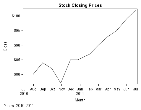
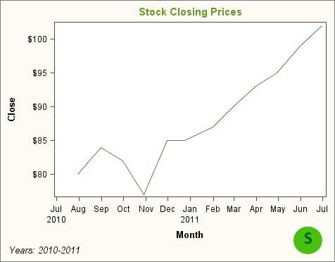
In this example, an
environmental engineering company wants to graph its stock closing
values for the past few months. The company plans to include the graph
in an online color presentation. Here are the high-level steps:
Data Used for This Example
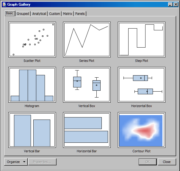
Create the Graph Using the ODS Graphics Designer
Step One: Create the Graph and Assign Data
-
In SAS, create the data set that you need for this example. Execute the code found in Data Used for This Example.