Dialog Controls
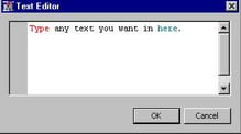
Text Editor
The most common example
of a text editor
Dialog Control is the Notes editor that is common to all
SAS distributed nodes. The notes editor simply provides a text file
in which the user might type notes related to a particular node in
a particular process flow diagram. This capability was extended to
extension nodes in Enterprise Miner 6.1. The XML Property configuration
for a Property with a text editor Dialog Control is as follows:
<Property
	description="Example of a text editor which enables
		you to enter and modify text in an external
		file."
	displayName="Text Editor"
	name="Code"
	type="String">

	<Control>
		<Dialog
			showValue="N"
			allowTyping="Y"
			class="com.sas.analytics.eminer.visuals.
			CodeNodeScoreCodeEditor">
			<Option name="key" value="CODE"/>
		</Dialog>
	</Control>
</Property>
First, notice the
class attribute of the Dialog element. You must copy that value verbatim. Second , notice the Option element. The Option element
has two attributes: name and value. The name attribute has
a value of "key" and the value attribute
has a value of "CODE". This is simply a different syntax for declaring
that this Dialog Control has a key="CODE". The explanation for why
the syntax for this type of control is different from all the other
controls that have a key attribute is beyond the scope of this discussion.
Registering the key
this way informs Enterprise Miner that the text that the user enters
into the editor is to be stored in a file named CODE.sas. When
property="Y", the contents of the editor are copied
along if you use a cut-and-paste action to make a copy of the node.
When property="N", the contents of the editor
are not preserved if you use a cut-and-paste action to make a copy
of the node. No other server code is required for this type of Dialog Control.
The user can then type
any text that they want in the editor. When the user clicks OK, the
file is saved under the name CODE.sas in the extension node's directory
for that particular process flow diagram. For example, if the projects
directory is
c:\emprojects and the
project name is "extension nodes", then CODE.sas is created in c:\emprojects\extension nodes\Workspaces\EMWS\EXMPL.
Interactions Editor
When developing statistical
models, it is common to include interactions between explanatory variables
in your model. For example, if you have the variables A and B, their
interaction is written A*B. An interaction editor provides a way for
a user to manually construct a collection of interactions that can
be used by your extension node.
The XML Property configuration
for a Property with an interactions editor
Dialog Control is as follows:
<Property
	type="String"
	name="Interaction"
	displayName="Interactions Editor"
	description="Example of an Interaction Editor.">

	<Control>
		<Dialog
			showValue="N"
			allowTyping="N"
			class="com.sas.analytics.eminer.visuals.
			InteractionsEditorDialog" >

			<Option
				name="Key"
				value="INTERACTION"/>
			<Option
				name="MainEffect"
				value="N"/>
			<Option
				name="MaxTerms"
				value="2"/>
			<Option
				name="Open"
				value="openInteractionTable"/>
			<Option
				name="Close"
				value="closeInteractionTable"/>
			<Option
				name="IntervalVariable"
				value="N"/>
		</Dialog>
	</Control>
</Property>
The
class attribute of the Dialog element uniquely
distinguishes this Dialog Control from the other type of Dialog Control elements and must be copied verbatim. Each of
the Option elements has two attributes: name and value. These Option elements and their attributes determine the interactions
editor's capabilities.
The first
Option element has a name attribute
of "key" and the value attribute has a value
of "INTERACTION". This is simply a different syntax for declaring
that this Dialog Control has a key="INTERACTION". The explanation
for why the syntax for this type of control is different from all
the other controls that have a key attribute
is beyond the scope of this discussion.
In the second
Option element, name="MainEffect" and value="N". This indicates that the
interactions editor is not to create an interaction that consists
of just a main effect. That is, all interactions must include at least
two terms. If value="Y", then an interaction
can consist of a main effect. That is, an interaction can consist
of a single term.
In the third
Option element, name="MaxTerms" and value="2". This indicates that the
maximum number of terms that can be included in an interaction is
2. The value attribute can have a range between
2 and 6.
The third and fourth
Option elements represent an alternative syntax for
the Actions elements that appeared in other Control elements. You must have at least one of these Option elements. You can write server code that is associated
with the name that you provide in the value attribute of these Option elements, but
it is optional. The explanation for why the syntax for this type of
control is different from all the other controls that have Actions elements is beyond the scope of this discussion.
In the final
Option element, name="IntervalVariable" and value="N". This indicates that interval
variables should not be used to populate the list of variables from
which the interactions are generated. When value="Y", then interval variables can be included in the list.
%em_register(key=INTERACTION, type=DATA);

data &em_user_interaction;
	length key 8 Term $32;
	stop;
run;
The first line of code
registers the key that appears in the first
Option element in the example XML above. The DATA step programming generates
an empty data set that has two variables: a numeric variable named
key and a string variable named Term.
Finally, before the
interactions editor can be populated with variable names, there must
be a data source node preceding your extension node in the process
flow diagram. For example, suppose you have the following process
flow diagram:
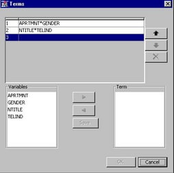
When the user clicks
on the  icon next to the interactions editor property the
following window appears:
 icon next to the interactions editor property the
following window appears:
When the user constructs
interactions, saves them, and clicks OK, Enterprise Miner creates
the Emws.Exmpl_interaction data set. For example, suppose the user
had selected APRTMNT and GENDER for the first interaction, and NTITLE
and TELIND for the second interaction, as depicted above. When the
user clicks OK, Emws.Exmpl_interaction appears
as follows:


