Understanding Attachments
Introduction
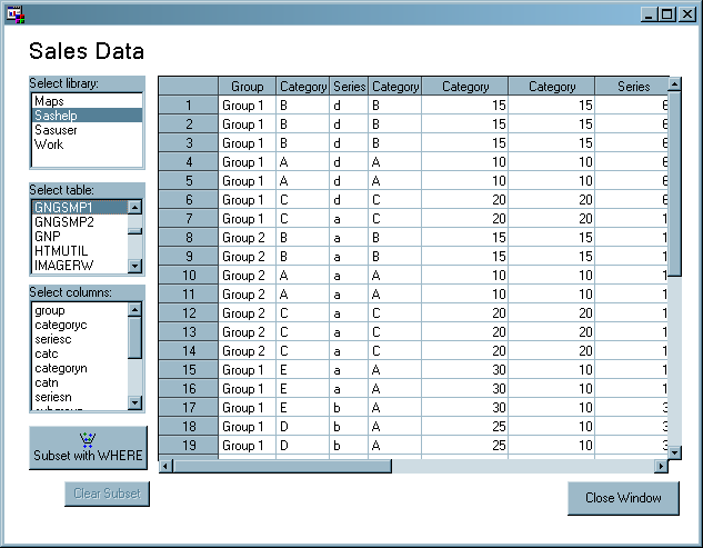
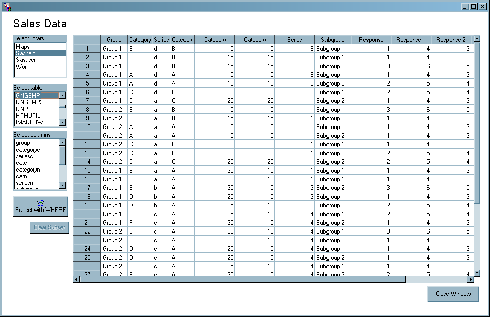
Attachments control the spatial relationships between
the graphical user interface elements on a window when the window
is resized. For example, with the appropriate attachments defined,
you can make a control expand when the user enlarges the window, enabling
the user to see more data. With a few simple attachments you can greatly
increase the utility of an application.
Attachment Points
You define attachments between a control and the edge
of the frame, or between the edge or center of two controls.
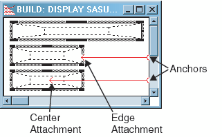
An attachment to the
edge of a control causes that edge to move when the other end of the
attachment (the anchor) is moved. An attachment to the center of a
control causes the entire control to move when the anchor for that
attachment is moved. Attachments are represented as arrows in the
graphical user interface.
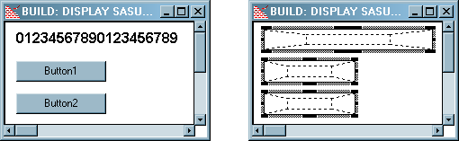
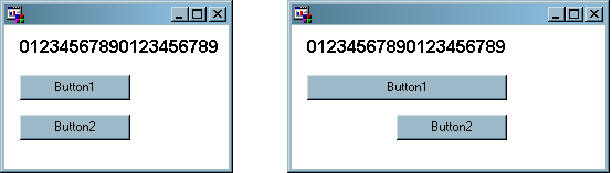
In the following display
the top Push Button control is attached from its right edge to the
right edge of the frame. The lower Push Button control is attached
from its center to the right edge of the frame.
Attachment Direction and Type
When you start defining
attachments, the Define Attachment dialog box appears so that you
can select the direction and type of attachment.
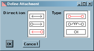
The direction of the attachment
governs which control changes when the anchor of the attachment is
moved. The control that the attachment arrow points to responds to
the moving of the anchor. Remember that an attachment can be anchored
to the edge or center of another control, or to the edge of the frame.
The left arrow direction is the default attachment direction, and
it is the only direction that is used in the example later in this
appendix.


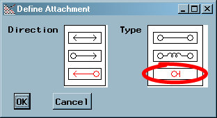
The type of attachment defines
the distance between the anchor and the arrow either in terms of pixels
between the points (an absolute attachment type), or as a percentage
of space between the points (a relative attachment type). The absolute
attachment type is the default attachment type, and it is the only
type of attachment that is used in the example later in this appendix.
|
Deletes attachments
(see Deleting and Altering Attachments)
|


Moving Controls That Are Attached
Before you define
any attachments, you should adjust the size of the frame and arrange
the controls as you want them to be displayed at run time. Once defined,
attachments are honored at build time, and if you move an anchor (on
a control or a frame), any attached controls are moved or resized
according to the attachments.
Deleting and Altering Attachments
For More Information about Attachments
There are many other
ways to control screen geometry using attachments. For more information,
see the Guide to SAS/AF Applications Development, available at support.sas.com/documentation/onlinedoc/af/.
Copyright © SAS Institute Inc. All rights reserved.