Creating a Process Job
Overview
You can create a process job that combines data processing with conditional processing. The process flow in the job supports logical decisions, looping, events and other features that are not available in a data job flow. Data Job nodes can be added to a process flow to encapsulate all of the data processing power of a data job into a node in the process flow. To create a process job, perform the following tasks:
- Plan the Job
- Add a New Process Job
- Add Source Data
- Read In Source Data
- Configure the End Condition
- Configure the Data Condition
- Set Up the Data Job Node
This section illustrates these tasks with a sample job named dmsample_echo_2, which is based on the dmsample_echo job that is included with the SAS Sample repository. The dmsample_echo_2 job contains the same nodes as dmsample_echo, but the nodes have been renamed to better indicate the role they play in the flow. The dmsample_echo_2 job is shown in the following display:

In the process flow for the current example:
- The State Table node is an Echo node that writes a small sample of default values to a work table. Each row in the table contains one two-letter state code. The work table has three rows, one row each for the state codes: NC, VA, and CA.
- The Read State Codes node is a Process Flow Work Table Reader node that reads the output table from the previous node one row at a time, with each execution of the process flow. (Subsequent nodes in the flow require a single state code, such as NC, VA, or CA.)
- The EOF Not Reached node is an If-Then node that reads a single state code from the previous node, and then evaluates the expression EOF=0, which means "end-of-file marker false" (not found). When the expression is false (the end-of-file marker is found) that result is sent to an Echo node named End of File. This is just a way of recording the fact that the end of the file was reached. When the expression is true (the end-of-file marker is not found), the Data Job node called Get Records by State is executed.
- The Get Records by State node is a Data Job node that retrieves a set of customer records where the customer’s address includes the selected state code from the Read State Codes node. It then saves the matching records to a table whose name includes the selected state code (such as table_name_NC and table_name_VA).
Plan the Job
The first task in creating a process job is to plan the flow. One way to start is to write a high-level description of the flow. For the current example job, the high-level description could read as follows:
Read a single state code from a table that contains a number of two-letter state codes. Retrieve a set of customer records where the customer’s address includes the selected state code. Save the matching records to a table whose name includes the selected state code. Repeat these tasks for each state in the state code table until the end-of-file marker is found.
Next, review the goals that you need to reach and determine which process job nodes are most appropriate for you to use. For an overview of all process job nodes, see Process Job Nodes. You will need nodes such as the following:
- One or more nodes that will specify a data source such as a table or a text file. In a process job, a Data Job node is often used to provide source data in a form that is usable by the other nodes in the job. The sample process jobs dmsample_event and dmsample_process take this approach. In the current example, two process nodes are used: an Echo node and a Process Flow Work Table Reader node.
- One or more nodes that provide conditional processing. These are the nodes that support logical decisions, looping, events and similar features. In the current example, an If-Then node (EOF Not Reached?) conditionally executes the Data Job node (Get Records by State).
- One or more nodes that provide data processing. Typically you will add one or more Data Job nodes to perform data processing tasks. In the current example, the Data Job node Get Records by State retrieves a set of customer records where the customer’s address includes the selected state code from the Read State Codes node. It then saves the matching records to a table whose name includes the selected state code.
After you have a general idea of what nodes you need and how they should be connected in a flow, you are ready to add a new process job.
Add a New Process Job
You can create a new process job to create flows that support logical decisions, looping, events, error handling, parallelization, and similar tasks.
Here is one way to create a process job:
- Click New in the Main Menu. Then, click Process Job.
- Enter a name for the process job in the Name field (dmsample_echo_2, in this case).
The following restrictions apply to the name of a job that will be deployed to a SAS Data Management Server. To avoid problems, you might want to follow these restrictions for all jobs. A job name can contain any alpha-numeric characters, white spaces, and any characters from the following list:,.'[]{}()+=_-^%$@!~/\
SAS Data Management Server will not upload or list a job name with characters other than those cited above. - Specify a location for the process job in the Save in field.
- Click OK to save the new process job.
Add Source Data
A Data Job node is often used to provide source data in a form that is usable by the other nodes in a process job. The sample process jobs dmsample_event and dmsample_process take this approach. The dmsample_echo_2 job, however, uses an Echo node (which is renamed to State Table) that writes a small sample of data to a temporary work table. The temporary work table then provides the source data to the rest of the job.
Perform the following tasks to add an Echo node, rename it, and specify a set of default values:
- Open the dmsample_echo_2 job.
- Expand the Utilities folder in the Nodes tree and select an Echo node.
- Drop the Echo node in the flow editor.
- Open the Echo node and click Properties.
- Enter a descriptive name, such as State Table, in the Name field.
- Click Inputs.
- Click New and select New Input Table.
- Enter the name of your input table, such as States_Table. Click OK.
- Click Edit Default Value.
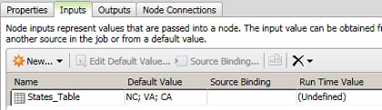
- Click New Row as needed to add default values for your input table. In this case, add NC, VA, and CA and click OK. The fully defined input is shown in the following display:
- Click Outputs to verify that States_Table has been automatically created in the job's outputs.
- Return to the sample job.
At this point, the sample job has a State Table node that creates a temporary work table named States_Table that contains three default state codes. These three state codes will be the input to the process job. However, the kind of processing that will be done in the sample job requires that one row of data be processed at a time. Accordingly, the next step is to add a node that will read one row of data in one pass of the input table.
Read In Source Data
The next stage in the sample process job configures a Process Flow Work Table Reader node to read one row of data at a time from a work table and write that row to an output table. This output table will be read by subsequent nodes in the job. Perform the following steps to rename the node and bind the default input table to the output table from the State Table node:
- Expand the Utilities folder in the Nodes tree and select a Process Flow Work Table Reader node.
- Drop the node in the flow editor and connect it to the State Table node.
- Open the Process Flow Work Table Reader node and click Properties.
- Enter a descriptive name, such as Read/Write State Codes, in the Name field.
- Click Inputs.
- Select the TABLE row and click Source Binding to access the Source Table page of the Source Binding wizard.
- Expand the object for the State Table node and select the States_Table input table. Then click Next to access the Source Columns page of the Source Binding wizard.
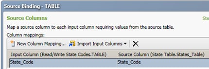
- Click Import Input Columns and select From Source Table. Because the source table only includes one column, the mapping shown in the following display is automatically created:
- Click Finish to save the source binding.
- Select the READMODE row. Then, click Edit Default Value.
- Enter NEXTROW and click OK. The NEXTROW value invokes an SQL option that makes the node read the next row in each pass of the table. Note that you can put the cursor over a row name to see a list of the available SQL options that describes the purpose of each option. The text for READMODE states the following: 'SINGLEROW' reads a row specified by index. 'NEXTROW' reads the next row in the set.
- Click Outputs. The output field that is specified in the field mappings on the Inputs tab is automatically added to the Outputs tab.
- Return to the sample job and save your changes to the job.
So far, you have created a flow which brings data into the job and refines that data so that it will be usable by the nodes that come next. You can click Run Process Job to see whether you have made any errors to this point. The goal of this trial run is not to get usable output. Instead, it enables you to verify that you have not specified any invalid settings for the current flow. When you have no errors, you can move on to the next node in the job.
Configure the End Condition
Process jobs can include decision nodes for conditional processing. The job in the current example includes an If-Then node that determines whether the EOF marker has been reached for the input table. Perform the following steps to add an If Then node to the job, rename the node, and specify each of the two outcomes that could result from running this node:
- Expand the Utilities folder in the Nodes tree and select an If Then node.
- Drop the If Then node in the flow editor and connect it the Read/Write State Codes node.
- Open the If Then node and click Properties.
- Enter a descriptive name, such as EOF Not Reached?, in the Name field.
- Click If Then.
- Begin to configure the first condition by entering EOF in the left Operand field.
- Select Equal to in the Operator field.
- Enter 0 in the right Operand field.
- Click Inputs.
- Select the EOF row and click Source Binding and access the Source Binding dialog.
- Expand the object for the Read/Write State Codes node and select the _EOF job variable.
- Click OK to save the source binding and close the dialog.
- Return to the flow editor for the sample job.
- Expand the Utilities folder in the Nodes tree and select an Echo node.
- Open the Echo node and click Properties.
- Enter an appropriate name, such as End of File, in the Name field. This node serves as a placeholder for the FALSE condition, as shown in the following display:

This output of the conditional evaluates to FALSE. It is not true that the end of the file has not been reached. In other words, it is true that the end of the file has been reached. There are no values left to process.
Configure the Data Condition
The remaining condition processes the data in the rows that evaluate to TRUE. This processing is performed in a Data Job node, which you need to add when you want to process significant amounts of data in a process job. The process flow in a process job is mainly used to launch processes and make decisions. It can execute based on input parameters, produce output parameters, and logically decide which node to execute next.
In this sample job, the Data Job node contains nodes that take a state code such as NC and use that code to retrieve records where State=NC (for example). Then, these nodes write the results to a table with the state code as part of the table name (such as TableName_StateCode). You use the properties of the Data Job node to specify a variable that brings the state code that is output from the process job (from the Read/Write State Codes node) into the Data Job node for processing.
Perform the following steps to add the Data Job node and specify this variable:
- Expand the Data Job folder in the Nodes tree and select a Data Job node.
- Drop the Data Job node in the flow editor.
- Open the Data Job node and click Properties.
- Enter a descriptive name, such as Get Records by State, in the Name field.
- Return to the flow editor for the sample job.
- Draw a connection from the EOF Not Reached? node to the Get Records by State node. The Get Records by State node now receives the output of the TRUE condition from the EOF Not Reached? node as its input. Thus, the EOF Not Reached? node feeds data to the Get Records by State node until it reaches the end of the file and triggers the FALSE condition in the EOF Not Reached? node.
- Draw a connection from the Get Records by State node to the Read State Codes node. The Read State Codes node now receives the output of the Get Records by State node one of its inputs.
- Open the Get Records by State node.
- Click Variables.
- Click Insert New Variable.
- Define a new variable. Name it STATE and select Input in the External Use column.
- Click Inputs.
- Select the STATE row and click Source Binding to access the Source Binding dialog.
- Expand the object for the Read/Write State Codes node and select the State Code job variable.
- Click OK to save the source binding and close the dialog.
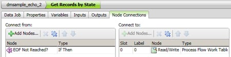
- Click Node Connections to review the connections that you have established, as shown in the following display:
Set Up the Data Job Node
The data flow contained in the Get Records by State node processes the data that satisfies the TRUE condition of the if/then processing in the conditional. It uses the following nodes:
- Select from CONTACTS is an SQL Query node that retrieves a set of customer records where the customer’s address includes the state code that is contained in the STATE variable. The value in the STATE variable is passed in from the process job. In the current example, the Contacts table is contained in the SAS Sample connection.
- CONTACTS in STATE is a Data Target (Insert) node that writes the selected customer records to a table that has a STATE suffix on the table name. The current example uses the SAS Sample connection to write the new tables.
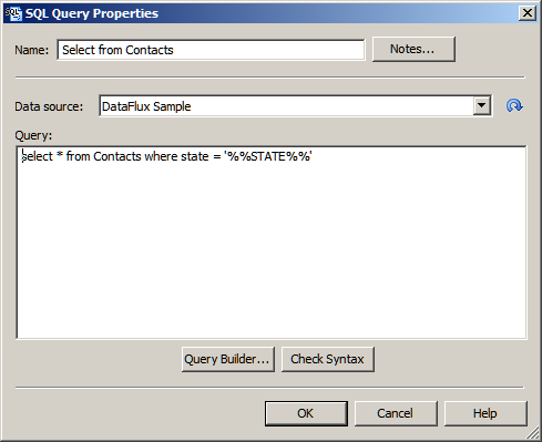
For the current example, we want to select all records from the Contacts table in the SAS Sample connection where the state field equals the value of the STATE input variable that is passed in from the process job. The following query selects those records:
select * from Contacts where state = '%%STATE%%'
Begin by adding an SQL Query node to the flow in the Get Records by State node. Then specify an appropriate SELECT statement. Perform the following steps:
- Open the Get Records by State node.
- Expand the Data Inputs folder in the Nodes tree and select an SQL Query node.
- Drop the SQL Query node in the flow editor.
- Double-click the SQL Query node to open its properties dialog. Select Open standard dialog in the dialog box that displays.
- Enter a descriptive name, such as Select from CONTACTS, in the Name field.
- Enter the SQL query in the Select from CONTACTS node. You can use the Query Builder to build a query. You can also simply enter the query manually in the Query field, as shown in the following display:
- Click Check Syntax to check your syntax. Then click OK to save the query and close the dialog.
Now you can add a Data Target (Insert) node and specify an appropriate insert statement. Perform the following steps:
- Make sure that you have returned to the flow editor for the Get Records by State node.
- Expand the Data Outputs folder in the Nodes tree and select a Data Target (Insert) node.
- Drop the Data Target (Insert) node in the flow editor.
- Double-click the Data Target node to open its Properties dialog. Select Open standard dialog in the dialog box that displays.
- Enter a descriptive name, such as CONTACTS in STATE, in the Name field.
- Verify that all of the output fields in the Available field are displayed in the Selected field. You also need to modify the value in the Output table field, but you must do that in the Advanced Properties dialog. Click OK to save the standard properties and close the dialog.
- Double-click the Data Target node to open its Advanced Properties dialog. Select Open advanced dialog in the dialog box that displays.
- Select the row for the DSN job variable.
- Double-click the Default Value column and enter the DSN, which is DSN=SAS Sample;DFXTYPE=ODBC for this example.
- Select the row for the TABLE_NAME job variable.
- Double-click the Default Value column and enter the file name that includes the macro, which is dmsample_echo_%%STATE%% for this example.
- Click OK to save the value and close the Advanced Properties dialog. The data job in the Get Records by State node should now be complete.
- Return to the process job. Click Run Process Job to run the job.
- Review the Log tab to ensure that the job completes successfully.
- Check the SAS Sample folder in the Data Connections riser. Verify that the output tables are created (such as dmsample_echo_CA).