Generating an Entity Resolution File
Overview
You can merge records from multiple files or duplicate records within a single file so that records referring to the same physical object such as an individual, company, or product are treated as a single record. These records are matched based on the information that they have in common. Of course, the more information held in common among the records, the higher the confidence in the match.
You can create a data job to prepare an entity resolution file by performing the following tasks:
- Create an Entity Resolution Data Job
- Generate Match Codes
- Set Clustering Properties
- Identify Surviving Records
- Prepare the Entity Resolution File and Run the Job
Create an Entity Resolution Data Job
You can create a data job. Then, you can populate it with the nodes that you need to merge your data and generate an entity resolution file. Perform the following steps:
- Open a data job.
- Open the Data Inputs folder in the Nodes tree. Select the Data Source node and drop it into the data flow.
- Open the Entity Resolution folder in the Nodes tree. Select the Match Codes node and drop it into the data flow. Then, connect the Data Source node to the node.
- Select the Clustering node and drop it into the data flow. Then, connect the Match Codes node to the Clustering node.
- Select the Surviving Record Identification node and drop it into the data flow. Then, connect the Clustering node to the Surviving Record Identification node.
- Open the Data Outputs folder in the Nodes tree. Select the Entity Resolution File Output node and drop it into the data flow. Then, connect the Surviving Record Identification node to the Entity Resolution File Output node.
- Double-click the Data Source node to display its properties window. Specify an input table that contains the data that you need to merge and process for entity resolution. For example, you could select a Contacts table that combines data from the other tables in the data connection. You could also move all of its fields to the Selected field in the Output fields section.
- Click OK to save the properties and close the window.
![]() Note: Because the data source for the Entity Resolution File Output node must have a primary key, only fields from the original source table should be selected as output fields. If a data job pushes copies of rows, then the input to the Entity Resolution Output node would contain more than one row with the same primary key value. The Entity Resolution Editor has no way to retrieve field values for separate rows that have the same primary key, so you must have a single primary key for the Entity Resolution Editor to find all the records for a cluster.
Note: Because the data source for the Entity Resolution File Output node must have a primary key, only fields from the original source table should be selected as output fields. If a data job pushes copies of rows, then the input to the Entity Resolution Output node would contain more than one row with the same primary key value. The Entity Resolution Editor has no way to retrieve field values for separate rows that have the same primary key, so you must have a single primary key for the Entity Resolution Editor to find all the records for a cluster.
![]() Note: You can use a text file as an input instead of a database table. To do this, replace the Data Source node with a Text File node and select a delimited text file as the input. Then click Options in the Entity Resolution File Output node and click Embed field data in the output file. When you view the entity resolution file created in such a job, select Embedded data in the Entity Resolution file in the Data sources section of the Properties tab of the entity resolution viewer.
Note: You can use a text file as an input instead of a database table. To do this, replace the Data Source node with a Text File node and select a delimited text file as the input. Then click Options in the Entity Resolution File Output node and click Embed field data in the output file. When you view the entity resolution file created in such a job, select Embedded data in the Entity Resolution file in the Data sources section of the Properties tab of the entity resolution viewer.
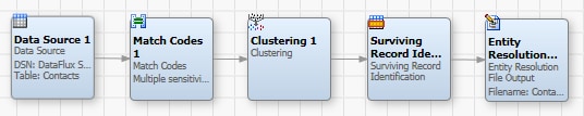
The following display shows a sample entity resolution flow:
Generate Match Codes
You need to set the properties for the Match Codes node to determine how match codes are generated in the job. Perform the following steps:
- Double-click the Match Codes node to display its properties window.
- Select a Quality Knowledge Base locale for the match codes.
- If you want to enable multiple match codes for source fields, select the Allow generation of multiple match codes per definition for each sensitivity check box. Multiple match codes enable you to assign a source field to multiple clusters. This function can be useful when the clustering algorithm cannot figure out the one best cluster to place a field. Instead, the job can generate multiple target records that can be distributed to multiple related record clusters where they can be resolved in the entity resolution process.
- Select your match code fields and move them to the Selected field in the Match code fields section. You need to use the drop-down menus to specify a definition and sensitivity for each match code field. Note that an output name is created for each match code field that you create.
- Click Additional Outputs to add the fields to the output. You can add all of the fields in the table for this example.
- Click OK to save the properties and close the window.
Set Clustering Properties
You need to set the properties for the Clustering node to set the parameters for the clusters identified in your entity resolution file. Perform the following steps:
- Double-click the Clustering node to display its properties window.
- Specify a name for the cluster ID field, such as Clusters.
- Set cluster field values such as treating blank field values as nulls, sorting output by cluster numbers, and including both single- and multi_row clusters.
- Specify your cluster conditions. In this case, I am specifying CONTACT_MatchCode_Score and CONTACT_MatchCode conditions.
- Click Additional Outputs to add the fields to the output. You can add all of the available fields.
- Click OK to save the properties and close the window.
Note that clustering is the first step in entity resolution. It is used to put groups of related records in clusters by assigning each a cluster ID. Records in a set with the same cluster ID are considered to be in a cluster. Each cluster is treated as a group that is processed by other entity resolution nodes after the data is clustered . One node that works with clustered data is the Surviving Record Identification node. This node looks at the cluster and chooses a surviving record (which is an entity) and flags it. After that, the clusters can out to an entity resolution file. You can then examine the entity resolution file and manually select the surviving records.
A cluster can be created based on a single entity, where an entity is a single field or a collection of fields concatenated together. It can also be created based on a multiple entity, where matches within a condition are made across all entities of that condition. Within a condition, records will match if any of the specified conditions match each other. For example:
- If Email1 is specified as the only entity within a condition, then two records will match if their Email1 fields match. This is represented as Match (Email1)
- If Email1 and Email2 are combined into the sole single entity within a condition, then two records will match if the concatenations of Email1 and Email2 match. This is represented as Match (Email1+Email2)
- If Email1 and Email2 are specified as two individual entities within a condition, then two records will match if any of the fields match any other. This scenario includes cross matches: for example, Email1 in one record matches Email2 in another, and so on for all combinations. This type of match is represented as Cross match (Email1, Email2)
For example, a cluster can be created in which Field 1 would be one condition, and Fields 2 and 3 would be two separate entities of a second condition, as shown in the following table.
| Row ID | Field 1 | Field 2 | Field 3 | Cluster ID |
|---|---|---|---|---|
| 1 | jodoe | john.doe@corp1 | johndo@corp2 | 0 |
| 2 | johnd | johndo@corp2 | john.doe@corp1 | 0 |
When cluster conditions are based on a single or a concatenated entity, the two rows above cannot get clustered together. However, you typically would want them in the same cluster. Cluster conditions enable this cross match functionality. For example, cluster condition one can be Match(Field1), and cluster condition two can be Match or cross match(Field2, Field3). In this case, the second condition enables the Clustering node to cross match values from Field2 and Field3. This cross match makes the second condition as a whole into a match for these two data rows, which brings the rows into the same cluster. For more information about using one or more conditions, see the Clustering Node.
You can use a Cluster Engine log to track how many times a match was made by each of the clustering conditions. Then you can use this log to look at individual cluster rules for the whole data set and see how often they have contributed to clustering records together. This new information can help to identify whether the clustering conditions designed for the given Cluster data node in a job are working as expected.
Here is sample output text from a Cluster Engine log:
04-21_10:49:29 Stopped loading data
04-21_10:49:29 Loaded data contains 10000000 rows and takes up <1214 MB
04-21_10:49:30 min / max cluster IDs: 0 / 9990340
04-21_10:49:30 Number of matches by condition 1: 23338
04-21_10:49:30 Number of matches by condition 2: 23223
04-21_10:49:30 Number of matches by condition 3: 23055
04-21_10:49:30 Number of matches by condition 4: 23226
04-21_10:49:30 Number of unique clusters: 9907158
Enable the Cluster Engine log by entering cluster/log=1 in the etc/app.cfg file. Enabling CE log has no impact on clustering performance.
Identify Surviving Records
You need to set the properties for the Surviving Record Identification node to select a cluster ID field and the output fields for the entity resolution file. Perform the following tasks:
- Double-click the Surviving Record Identification node to display its properties window.
- Click the drop-down menu in Cluster ID field and select the ID that you specified in the Clustering node (Clusters).
- Review the Record rules field to examine the rules associated with selected cluster ID. Add or delete rules as needed.
- Move all of the output fields and clusters in the Available field to the Selected field.
- Click OK to save the properties and close the window.
Prepare the Entity Resolution File and Run the Job
You need to set the properties for the Entity Resolution File Output node to set parameters for the entity resolution file. Perform the following tasks:
- Double-click the Entity Resolution File Output node to display its properties window.
- Specify the properties for the entity resolution file. The properties for the sample job are displayed in the following table:
- Confidence value field: CONTACT_MatchCode_Score
- Surviving record ID field: SRID
- Source table: Commit every row
- Data removal: Delete duplicate records
- Delete flag fields: ID (populated from selected primary keys section in entity resolution properties)
- Audit file name: Specify any convenient value
- Click OK to save the properties and close the window.
- Run the job. The following display shows a portion of the log for the job:
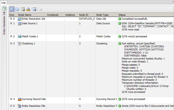
Note that if you selected Display file after job runs, the entity resolution file is displayed after a successful job submission. You can inspect the log by clicking the tab for the job.
| Property | Value |
|---|---|
| Cluster ID field | Clusters |
| Source table | Contracts |
| Output file | Specify a field in an accessible repository |
| Display file after job runs | Selected |
| Options |
|
| Target |
|
| Output fields | Specify all of the table fields (but not the clusters, SRID, and match codes. The SRID file (.SRI) must be output to the default location. This happens automatically if you when you click the "..." button.) |