DataFlux Data Management Studio 2.5: User Guide
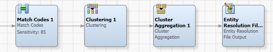
A simple data job using combination-based matching usually contains a Matchcodes node, a Clustering node, and a Cluster Aggregation node, in addition to the usual input and output nodes. This configuration is acceptable when there is only one data type ("field") that generates matchcodes with scores as seen in the following display:
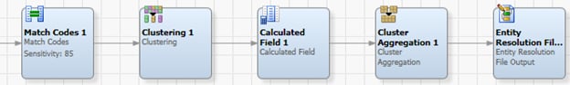
However, if matchcodes with scores are being generated from multiple fields, then an additional Calculated Field node is recommended to be placed before the Cluster Aggregation node:
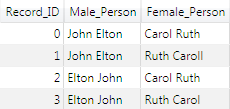
In the following discussion, outputs of each node are shown using simple example data. In this example, each record contains two personal names: a male name and a female name, as shown in example below. Record 1 differs from Record 0 by a transposition in the female name and a trivial character-level difference that is subsumed by reduction rules in the token processing. Record 2 differs from Record 0 by a transposition in the male name. Record 3 contains transpositions in both the male and female names. Assuming there is some ambiguity at the data entry stage, all these records might in fact refer to the same entity.
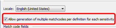
In order to effectively use a combination-based match definition in the Matchcodes node, that definition must, obviously, be selected for use on a field in the node’s properties. In addition, the Allow multiple matchcodes per definition for each sensitivity checkbox must be checked. This checkbox enables suggestion-based matching and combination-based matching, if present in the match definition.
![]() Note: The checkbox has no effect on match definitions that use neither combination-based nor suggestion-based matching.
Note: The checkbox has no effect on match definitions that use neither combination-based nor suggestion-based matching.
If the checkbox is checked, the Matchcodes node outputs an additional score field for each matchcode output field. These fields are created automatically and named XXX_Score, where XXX is the name of the matchcode output field. The score fields should be passed through any other nodes that follow the Matchcodes node.
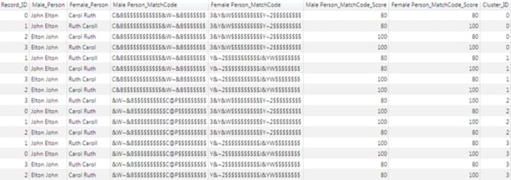
In the following example, the Matchcodes node has been set up to generate matchcodes on both the male and female persons' names.
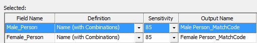
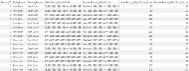
Because the match definition contains one token combination rule, in addition to the default rule, the match definition outputs up to two matchcodes for the male person’s name and up to two matchcodes for the female person's name. There could therefore be up to four rows output for each record. The matchcode output rows are shown in the following display:
No new actions need to be taken in the Clustering node when using combination-based matching, other than ensuring that the score fields are passed through to the next node via the Additional Outputs dialog box.
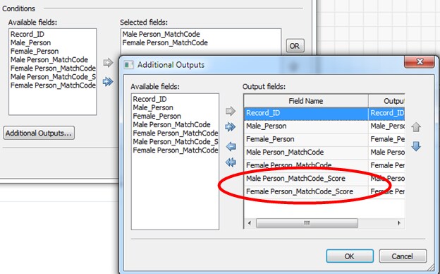
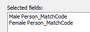
In the following example, the Clustering node is set up to cluster on both the matchcode for the male person's name and the matchcode for the female person’s name:
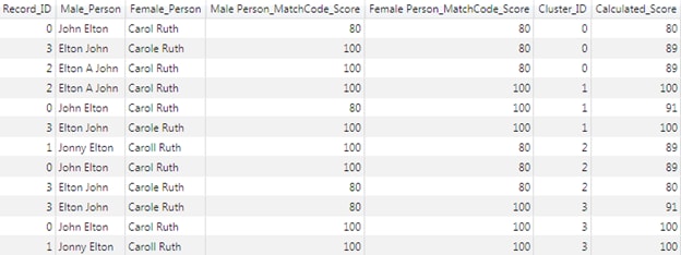
The output of the clustering node is shown in the following display. Notice that because all four records have produced the same four matchcodes, all of the records have been assigned to each of the four clusters.
The Calculated Field node is new in DM Studio 2.2 and is categorized under the Utilities folder. The Calculated Field node allows several numeric fields to be mathematically combined together into a new field. This node is a general-purpose utility node and has many applications in data jobs. When working with combination-based matching, it is used to combine the scores from several matchcode fields into a single score. The weight of each individual field in the combined score reflects how important the field is thought to be, relative to the other fields. While it is not strictly necessary to combine the scores, it is often convenient for the user to see a single numeric value for each record in a cluster.
The Selected Fields grid contains a weight for each field. For each record, the weighted values are combined into a new value using the selected Operation (for example, by taking the mean of the weighted values). Then the result is placed into a new Output Field.
The available choices for the Operation are:
In the following example, because there are two matchcode fields, there are two score fields as well. In this scenario, let it be assumed that for some reason the female person's name is more significant to the match than the male person’s. This example shows the node properties when the score for the matchcode generated from the female person’s name is weighted slightly higher:
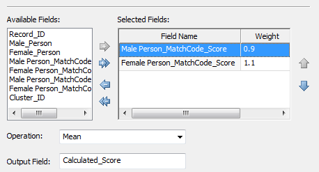
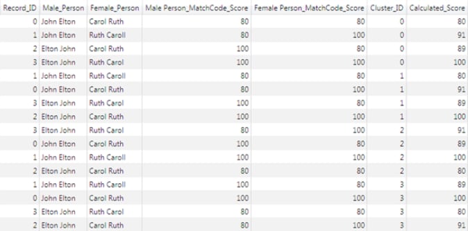
After setting up the Calculated Field node to combine the two scores into a new field using the Mean operation, the output rows are shown:
The Cluster Aggregation node is new in DM Studio 2.2 and is categorized under Entity Resolution folder. Its purpose is to combine several clusters which contain exactly the same set of records.
It is a common occurrence for two or more clusters to contain the same set of records, but with different scores for the matchcodes, as seen in the example. The Cluster Aggregation node constructs one cluster from the set to represent them all, and discards the rest.
While it is not strictly necessary to perform cluster aggregation, it is usually convenient because this frees the user from having to examine and resolve multiple clusters with the same memberships during the entity resolution stage. The option to remove subclusters (see below) is also sometimes helpful in reducing the amount of information presented to the user.
To set the properties of this node, open the Properties window:
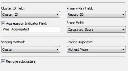
After specifying which fields are the Cluster ID Field, the Primary Key Field and the Score Field, the scores are aggregated within each cluster using the selected Scoring Method and Scoring Algorithm. The possible choices for each scoring method and algorithm, together with their effects, are described in the table below:
| Scoring Method | Scoring Algorithm | Effect |
|---|---|---|
| Record | Maximum | Each record in the aggregated cluster has the maximum score of that record in all clusters where it appears |
| Mean | Each record in the aggregated cluster has the mean score of that record in all clusters where it appears | |
| Mean with scaling | Same as mean, but the scores are scaled to span the same range as the original scores | |
| Median | Each record in the aggregated cluster has the median score of that record in all clusters where it appears | |
| Minimum | Each record in the aggregated cluster has the minimum score of that record in all clusters where it appears | |
| Cluster | Highest Maximum | The maximum value in each cluster is computed, and the cluster with the highest maximum is taken as the aggregated cluster |
| Highest Mean | The mean value in each cluster is computed, and the cluster with the highest mean is taken as the aggregated cluster | |
| Highest Minimum | The minimum value in each cluster is computed, and the cluster with the highest minimum is taken as the aggregated cluster | |
| Lowest Maximum | The maximum value in each cluster is computed, and the cluster with the lowest maximum is taken as the aggregated cluster | |
| Lowest Mean | The mean value in each cluster is computed, and the cluster with the lowest mean is taken as the aggregated cluster | |
| Lowest Minimum | The minimum value in each cluster is computed, and the cluster with the lowest minimum is taken as the aggregated cluster |
Clearly, aggregation is not applied to clusters whose member records form a unique set, because there is no other cluster with which they could be aggregated. A visible indicator of which clusters are affected by aggregation is provided by the optional additional field called the Aggregation Indicator Field.
If the option to Remove subclusters is checked, this causes any cluster that is a subset of another cluster to be silently suppressed from the output. Cluster A is a subset of cluster B if all the records in cluster A are also contained in cluster B, and cluster B is larger than cluster A.
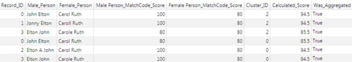
In the following example, the complete output of the Cluster Aggregation node is shown. Notice that instead of four clusters, there is now only one cluster, cluster 0, which contains all the records. The 'was_aggregated' flag is set to true because cluster 0 was aggregated from four clusters containing the same records.
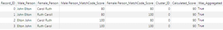
The four clusters obtained from the clustering node have now been reduced to one. This illustrates the utility of the Cluster Aggregation node in reducing the amount of data displayed during the following entity resolution stage and simplifying the cluster resolution effort. In this simple example, the only action now necessary in the entity resolution step is to assign a surviving record to this cluster.
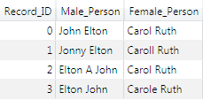
In order to illustrate more of the entity resolution workflow, a different example shows the input data below. Here, the differences in the female name are trivial and the only transpositions occur in the male name. Records 1 and 2 contain male names that are non-transposable by the rules of the match definition previously constructed: Record 1 has the given name "JONNY", which is not a common family name, and Record 2 contains a middle initial.
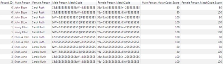
The output of the Matchcodes node for this data set is in the following display. In contrast to the first example, because Records 1 and 2 have non-transposable male names, they produce only two matchcodes.
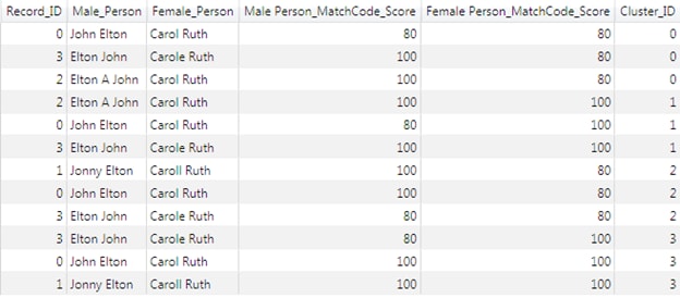
This display shows the output of the Clustering node. There are four clusters, but this time each cluster only contains three records. Two of the clusters contain records 0, 2 and 3; the other two clusters contain records 0, 1 and 3. After cluster aggregation, only two clusters would remain.
The following display shows the output of the Calculated Field node:
The properties settings and output of the Cluster Aggregation node are below. This time, the scoring method and algorithm have been set to 'Record' and 'Mean' respectively. As expected, the Cluster Aggregation output contains two clusters.

The two remaining clusters share records 0 and 3; or, equivalently, records 0 and 3 have been provisionally assigned to two clusters. At this point, the entity resolution step must be carried out to assign each record to exactly one cluster.
If matchcodes are being generated for entity resolution, then the aggregated cluster output should be fed to an Entity Resolution File Output node. General usage of this node is documented in the existing DM Studio Help topic "Entity Resolution File Output Node" and in the section "Prepare the Entity Resolution File and Run the Job" within the Help topic "Generating an Entity Resolution File".
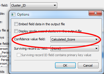
No special actions need to be taken when using combination-based matching, except for setting the Confidence value field. This should be set to the field that contains the matchcode score (or the calculated score arising from the Calculated Field node, if more than one input field is generating matchcodes), as shown below:
Note that if more than one field is generating matchcodes, those individual matchcode scores can still be passed to the entity resolution stage (for example, for informational purposes) by selecting them as output fields. Generating the calculated score and using it as the confidence value field simply provides a convenient single numeric value to represent the confidence of a record’s assignment to a certain cluster.
General usage of the entity resolution file is documented in the existing DM Studio Help topic "Working with an Entity Resolution File." When the file is generated using combination-based matching, the major difference from legacy matching is that records can exist in multiple clusters. Clusters that have at least one record in common are called related clusters.
When working with combination-based clusters, the goals are therefore to:
In the example, there are two clusters at the Entity Resolution input:
The following example shows that when the first cluster is selected in the cluster list, the other cluster is shown as a related cluster; this is because the clusters share records 0 and 3.
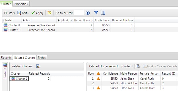
Another example shows the same display when the second cluster is selected. In both cases, the records, which are responsible for the relation between the clusters (records 0 and 3), are marked with an orange triangle.
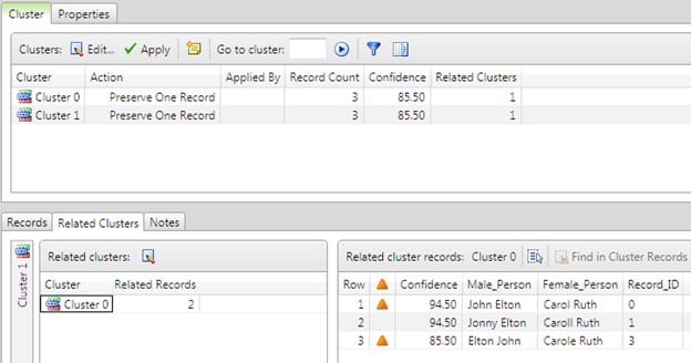
The user now needs to decide which cluster the records should ultimately be assigned to. Notice that Record 0 has higher score in the first cluster than in the second, while record 3 has a higher score in the second cluster than in the first. This indicates that, according to the rules of the match definition, record 0 has a higher confidence of belonging to the first cluster and record 3 has a higher confidence of belonging to the second cluster. The difference in scores arises because of the weight penalty assigned to the rule that transposes given and family names.
The cluster editing interface is shown below:
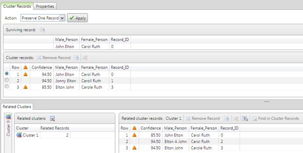
A highlighted record can be removed from a cluster in which it is contained. Alternatively, the highlighted record can be retained in the selected cluster and removed from all other related clusters. The menu icons for these actions are shown in the following example. (The same actions can also be accessed from the context menu.)

Assuming that the desired outcome is to assign record 0 to the first cluster and record 3 to the second, one way this can be achieved is by selecting record 0 in the first cluster and clicking Remove records from all related clusters. This removes record 0 from the second cluster. The equivalent action can then be repeated for record 3 in the second cluster.
At this point, all the records belong to exactly one cluster. All that is required now is to determine the surviving records for the clusters. Any one of the records in the cluster can be assigned in its entirety as the surviving record, or individual fields can be chosen from among the records in the cluster, as shown below. Alternatively, if none of the available alternatives is desired, text can be typed freely into any field.
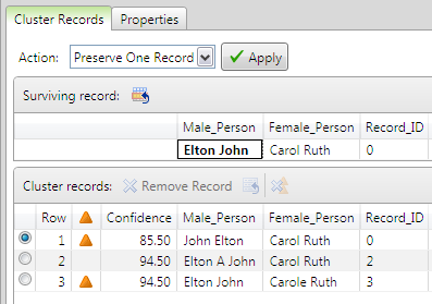
When the Apply button is clicked, the cluster is resolved using the selected Action. In this case, the surviving record replaces all the records in the cluster.
The amount of manual review effort expended at the entity resolution stage can often best be reduced by noticing common trends among records that are obviously incorrectly clustered, and suitably modifying the match definition(s) or job to help avoid these types of problems in the first place. For example, if there is a very common type of data entry error, factoring this knowledge into the match definition can improve the subjective quality of clustering. This helps limit the number of changes needed to assign the problematic records to the correct clusters.
It is strongly recommended that the Cluster Aggregation node be used. For most users, it is also helpful for the option Remove subclusters to be checked in this node. The use of this node greatly reduces the number of clusters that must be reviewed.
During the entity resolution stage, reviewers should proceed in this way:
|
Documentation Feedback: yourturn@sas.com
|
Doc ID: dfDMStd_CBM_datajob.html |