Using the Diagram Editor
Elements of a Process
Overview
Activities
Activities can be atomic
nodes (tasks) or can contain collections of related nodes (local subprocesses).
The process hierarchy is represented in the process tree as expandable
folders. Tasks are represented by an activity icon ( ) and the root workflow and its subprocesses are denoted
using the process icon (
) and the root workflow and its subprocesses are denoted
using the process icon ( ).
).
) and the root workflow and its subprocesses are denoted
using the process icon ().
Policies
Policies
encapsulate event-triggered, executable business logic that can reference
process data to add, change, or update peer processes at run time.
These events occur when there is a change in the process. Events can
be triggered when there is either a change in the state or status
of the process, generated by using a timer for single or repeated
actions, or received by external systems.
Process Diagram Elements
Global data objects,
policies, statuses, and participants are associated with the top-level
folders under the workflow root. Activities can also contain locally
defined data objects, policies, statuses, and participants. Local
elements exist in the context of a specific activity are accessible
only at the activity-level, not by the other tasks or subprocesses.
Data objects can be defined on the root or subprocess level, but the
visibility can be configured by enabling the Visible in
entire subtree option. Enabling this option means the
data definition is available to the children within that process level
for logical evaluation or policy execution. However, these global
elements are not recreated as local values associated with the child
elements.
Each process begins
with a Start node and contains one or more activities (tasks or subprocesses)
before terminating with at least one Stop node. Each new diagram includes
a Start and Stop node, but a single Stop node might terminate multiple
activities. Likewise, the Start node can be used to initiate multiple
activities.


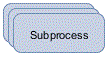
An activity element
with a stacked appearance represents a subprocess. A subprocess contains
one or more activities that might, in turn, represent subprocesses
resulting in a process hierarchy. You can create subprocesses and
edit the contained activities from the drawing editor.
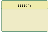
Swimlane elements are
used in SAS Workflow Studio to group activities assigned to the same
participant definition. They can be explicitly assigned to a Participant
object, or they can be implicitly assigned via a swimlane policy.
The swimlane policy derives the user, group, or role value defined
by the specified data object at run time.


You can use the drawing
tools in the toolbar to place activities on the diagram editor and
connect them using the Sequence Flow element. You can also select
and right-click any activity or connection on the diagram editor to
add objects. Alternatively, you might use the process tree pop-up
menus to add activities and other process elements.