Examples of Simulation Studio Models
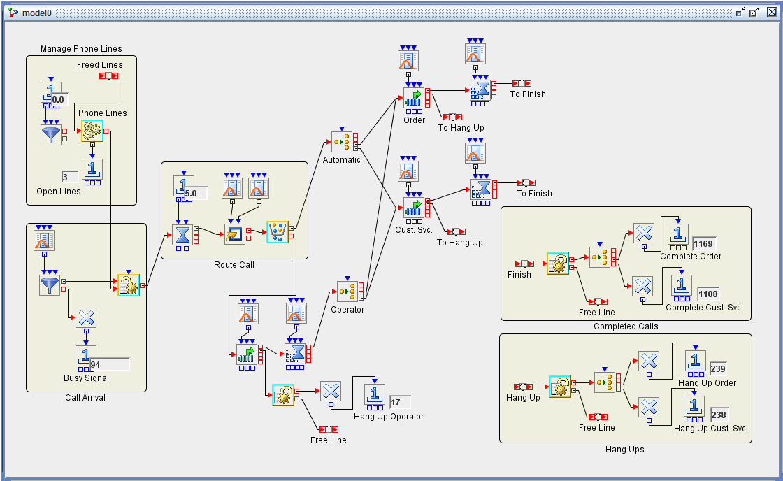
This example demonstrates the use of both regular entities and resource entities to model the operations and performance of an incoming call center, in which a finite number of telephone lines are allocated among callers who want to conduct one of two types of business. Several of the standard Simulation Studio blocks are used along with some advanced blocks and some blocks specialized for resource entities. The model is shown in Figure E.19. Callers choose whether to use the call center’s automated call routing system or to speak with an operator. They also choose one of two activities: placing an order or speaking with customer service. Calls might be lost initially due to a lack of open phone lines (the caller gets a busy signal) or when a caller is forced to wait an excessive amount of time to speak with an operator or service representative.
Note: Although the time units of the simulation clock in Simulation Studio do not denote any specific time units, for the purposes of this model each time unit represents one second.
The Manage Phone Lines section of the model creates and maintains the resource entities in this model, representing the available telephone lines in the call center. An Entity Generator block creates 15 Telephone Line resource entities at time zero and routes them to the Resource Pool block labeled Phone Lines; the Number Holder block attached to its OutLength port reports the current number of available lines.
In the Call Arrival section, incoming calls are created as regular entities. Calls arrive via an Entity Generator block according to an exponential distribution with mean 30. Each entity is created as a member of an entity type named Caller, with an attribute named Choice that is used to designate the type of business that the caller wishes to conduct. A second attribute, Operator, specifies whether the caller wishes to speak with an operator or use the automated routing system solely.
These Caller entities proceed immediately to a Seize block, which attempts to allocate one Telephone Line resource entity to the Caller entity. If no telephone lines are available, the caller receives a busy signal and hangs up; this is modeled by the Caller entity exiting its Entity Generator block via the OutBalk port to a Disposer block. A Number Holder blocks tallies these calls.
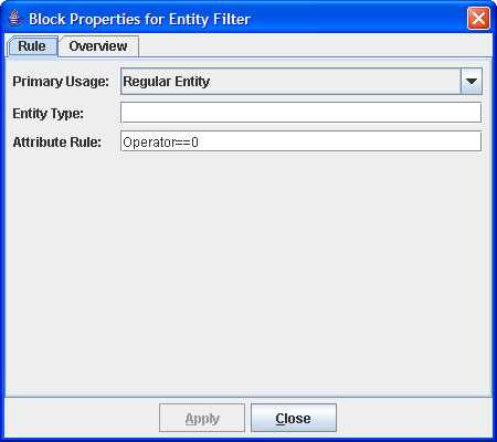
If a Telephone Line is allocated, the Caller entity moves next to the Route Call section of the model. A Delay block simulates the time (5 seconds) taken by the initial dialogue of the automated answering system, and the Caller entity moves next to a Modifier block that randomly assigns values to the Choice attribute (1=place order, 2=customer service) and the Operator attribute (0=use automated system, 1=speak with operator). An Entity Filter block checks the value of the Operator attribute, and routes the Caller entity accordingly. The properties dialog box for this Entity Filter block, shown in Figure E.20, show that it simply checks whether the value of Operator is equal to zero.
If the caller prefers to speak with an operator (the value of the Operator attribute is not zero), the Caller entity is routed to the lower section of the model, which consists chiefly of a Queue block (FIFO queueing policy) and a Server block (capacity 2, indicating two operators on staff). The Caller entity might renege from this queue, indicating a hang-up by a caller who has been waiting too long to speak with an operator. The distribution of the renege time is uniformly distributed from 75 to 120; this indicates that each caller waits at this point between 75 and 120 seconds before hanging up. Service time with an operator is exponentially distributed with mean 45 seconds.
If the caller hangs up while awaiting an operator, the Caller entity passes out the OutRenege port of the Queue block to a Release block that frees up the Telephone Line resource entity, sending it back to the Phone Lines Resource Pool block via a Connector. The Caller entity proceeds to a disposer, is counted, and exits the system.
If the caller completes service with the operator, the Caller entity moves next to the Operator Switch block, which routes the Caller entity according to the value of the Choice attribute. An identical Switch block, labeled Automatic, is encountered by Caller entities that exit the Entity Filter block with an Operator attribute value of zero. These two Switch blocks could easily be combined but are modeled separately for the sake of clarity.
The Switch blocks route Caller entities to either the Order queue or the Cust. Svc. queue, both located in the upper right corner of the model. The model is identical in each case, except for differences in renege time and service time distribution parameters. For each, the Caller entity might renege (the caller might hang up) and if so is routed (via a Connector) to the Hang Ups section of the model. Otherwise the Caller entity eventually proceeds to the corresponding Server block (capacity 4 for Order and 3 for Cust. Svc.) and then is routed (via a Connector) to the Completed Calls section of the model.
In both the Hang Ups section and the Completed Calls section the treatment of the Caller entity is identical. First, a Release block releases the Telephone Line resource entity back to the Phone Lines Resource Pool block. Next, a Switch block routes the Caller entity to a specific Disposer block and Number Holder block based on the value of the Choice attribute; this enables hang ups and completed calls according to the type of service desired or provided.
The model is run for 86,400 seconds, equal to 24 hours of continuous operation of the call center. Tracking of the number of busy signals, hang ups, and completed calls in each category can provide invaluable information about the performance of the call center under varying conditions. This model can be made even more useful by specifying key controls (number of lines, staffing levels, service times, and so on) as factors and key performance indicators (the aforementioned counts, staff utilization, queue lengths, and so on) as responses so that experimental design can be used to create a number of different scenarios for which the simulation can be run and the results tracked.