Logical Design: Constructing an Electronic System with a Minimum Number of Components
Logical circuits have a given number of inputs and one output.[13] Impulses may be applied to the inputs of a given logical circuit and it will respond either by giving an output (signal 1) or by giving no output (signal 0). The input impulses are of the same kind as the outputs, i.e. 1 (positive input) or 0 (no input).
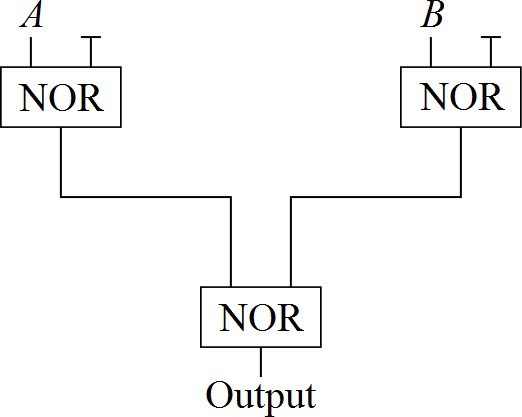
In this example a logical circuit is to be built up of NOR gates. A NOR gate is a device with two inputs and one output. It has the property that there is positive output (signal 1) if and only if neither input is positive, i.e. both inputs have value 0. By connecting such gates together with outputs from one gate possibly being inputs into another gate it is possible to construct a circuit to perform any desired logical function. For example the circuit illustrated in Figure 12.1 will respond to the inputs A and B in the way indicated by the truth table in Table 12.1.
The problem here is to construct a circuit using the minimum number of NOR gates which will perform the logical function specified by the truth table in Table 12.2. This problem, together with further references to it, is discussed in Williams (1974).
‘Fan-in’ and ‘fan-out’ are not permitted. That is, more than one output from a NOR gate cannot lead into one input, nor can one output lead into more than one input.
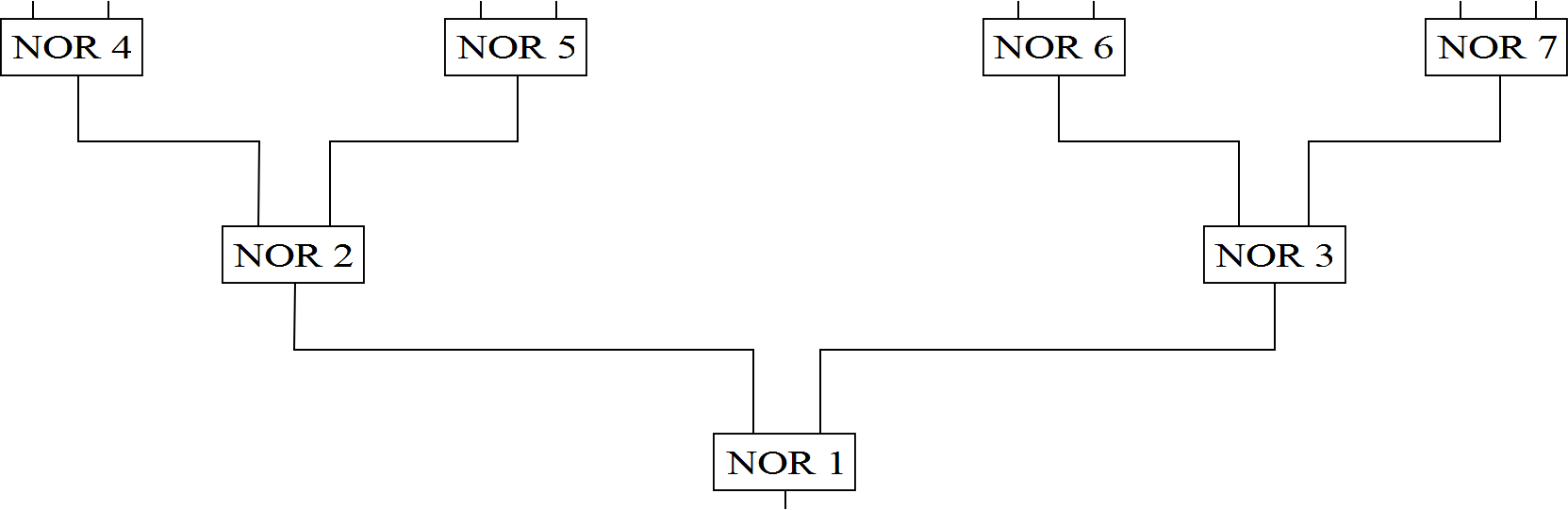
It may be assumed throughout that the optimal design is a ‘subnet’ of the ‘maximal’ net shown in Figure 12.2.