The first several PROC OPTMODEL statements declare index sets and read the input data:
proc optmodel;
   set <num,num> EDGES {1..2};
   read data edge_data1 into EDGES[1]=[i j];
   read data edge_data2 into EDGES[2]=[i j];
The following statements declare and initialize the NODES[g] sets and then use the INTER operator to store their elements in increasing order:
   set NODES {g in 1..2} init union {<i,j> in EDGES[g]} {i,j};
   for {g in 1..2} NODES[g] = 1..card(NODES[g]) inter NODES[g];
The following statements declare the remaining sets:
   set IJ = NODES[1] cross NODES[2];
   set EDGE_PAIRS = {<i,j> in IJ, <k,l> in IJ: i < k and j ne l and
      (<i,k> in EDGES[1]) and (<j,l> in EDGES[2])};
The following model declaration statements correspond directly to the mathematical programming formulation that is described earlier:
   /* Assign[i,j] = 1 if node i in NODES[1] assigned to node j in NODES[2] */
   var Assign {IJ} binary;

   /* IsCorrespondingEdge[i,j,k,l] = 1 if edge <i,k> in EDGES[1]
      corresponds to edge <j,l> in EDGES[2] */
   var IsCorrespondingEdge {EDGE_PAIRS} binary;

   /* maximize number of corresponding edges */
   max NumCorrespondingEdges =
      sum {<i,j,k,l> in EDGE_PAIRS} IsCorrespondingEdge[i,j,k,l];

   /* assign each i to at most one j */
   con Assign_i {i in NODES[1]}:
      sum {<(i),j> in IJ} Assign[i,j] <= 1;

   /* assign at most one i to each j */
   con Assign_j {j in NODES[2]}:
      sum {<i,(j)> in IJ} Assign[i,j] <= 1;

   /* disallow crossing edges */
   con NoCrossover {<i,j> in IJ, <k,l> in IJ: i < k and j > l}:
      Assign[i,j] + Assign[k,l] <= 1;

   /* if IsCorrespondingEdge[i,j,k,l] = 1 then Assign[i,j] = Assign[k,l] = 1 */
   con Corresponding1 {<i,j,k,l> in EDGE_PAIRS}:
      IsCorrespondingEdge[i,j,k,l] <= Assign[i,j];
   con Corresponding2 {<i,j,k,l> in EDGE_PAIRS}:
      IsCorrespondingEdge[i,j,k,l] <= Assign[k,l];
The following statements call the mixed integer linear programming solver and use the FILE and PUT statements to write log output to the listing:
   solve;
   file print;
   for {<i,j> in IJ: Assign[i,j].sol > 0.5}
      put ('Node '||i||' in graph 1 corresponds to node '||j||' in graph 2.');
   for {<i,j,k,l> in EDGE_PAIRS: IsCorrespondingEdge[i,j,k,l].sol > 0.5} do;
      put ('Edge ('||i||','||k||') in graph 1 corresponds to') @@;
      put ('edge ('||j||','||l||') in graph 2.');
   end;
quit;
Figure 29.5 shows the output from the mixed integer linear programming solver.
Figure 29.5: Output from Mixed Integer Linear Programming Solver
| Problem Summary | |
|---|---|
| Objective Sense | Maximization |
| Objective Function | NumCorrespondingEdges |
| Objective Type | Linear |
| Number of Variables | 179 |
| Bounded Above | 0 |
| Bounded Below | 0 |
| Bounded Below and Above | 179 |
| Free | 0 |
| Fixed | 0 |
| Binary | 179 |
| Integer | 0 |
| Number of Constraints | 2160 |
| Linear LE (<=) | 2160 |
| Linear EQ (=) | 0 |
| Linear GE (>=) | 0 |
| Linear Range | 0 |
| Constraint Coefficients | 4478 |
| Performance Information | |
|---|---|
| Execution Mode | Single-Machine |
| Number of Threads | 1 |
| Solution Summary | |
|---|---|
| Solver | MILP |
| Algorithm | Branch and Cut |
| Objective Function | NumCorrespondingEdges |
| Solution Status | Optimal |
| Objective Value | 5 |
| Relative Gap | 0 |
| Absolute Gap | 0 |
| Primal Infeasibility | 0 |
| Bound Infeasibility | 0 |
| Integer Infeasibility | 0 |
| Best Bound | 5 |
| Nodes | 1 |
| Iterations | 475 |
| Presolve Time | 0.08 |
| Solution Time | 0.19 |
Figure 29.6 shows the output from the PUT statements.
Figure 29.6: Output from PUT Statements
                             The OPTMODEL Procedure

Node 1 in graph 1 corresponds to node 2 in graph 2.
Node 2 in graph 1 corresponds to node 3 in graph 2.
Node 3 in graph 1 corresponds to node 4 in graph 2.
Node 4 in graph 1 corresponds to node 6 in graph 2.
Node 5 in graph 1 corresponds to node 7 in graph 2.
Node 6 in graph 1 corresponds to node 8 in graph 2.
Node 8 in graph 1 corresponds to node 10 in graph 2.
Node 9 in graph 1 corresponds to node 11 in graph 2.
Edge (1,2) in graph 1 corresponds to edge (2,3) in graph 2.
Edge (3,4) in graph 1 corresponds to edge (4,6) in graph 2.
Edge (3,5) in graph 1 corresponds to edge (4,7) in graph 2.
Edge (5,6) in graph 1 corresponds to edge (7,8) in graph 2.
Edge (8,9) in graph 1 corresponds to edge (10,11) in graph 2.
|
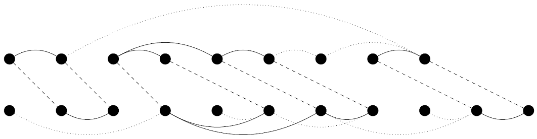
Figure 29.7 shows the optimal solution as a comparison between contact maps, with the matched nodes indicated by dashed lines and the edges of the isomorphic subgraphs highlighted.